2 interrupt mask (intmsk)-hdlc mode, Figure 28-3. intmsk mask bits, 3 channel mode register (chamr)-hdlc mode – Freescale Semiconductor MPC8260 User Manual
Page 856: Figure 28-4. channel mode register (chamr), Interrupt mask (intmsk)—hdlc mode -8, Channel mode register (chamr)—hdlc mode -8, Intmsk mask bits -8, Channel mode register (chamr) -8, Section 28.3.1.3, “channel mode register, Chamr)—hdlc mode
Multi-Channel Controllers (MCCs)
MPC8260 PowerQUICC II Family Reference Manual, Rev. 2
28-8
Freescale Semiconductor
28.3.1.2
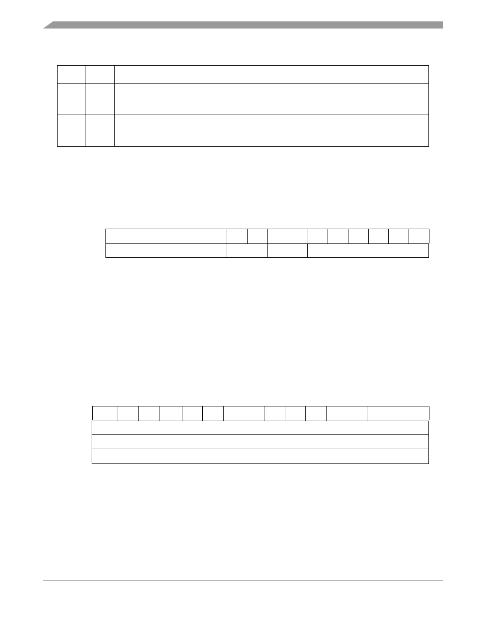
Interrupt Mask (INTMSK)—HDLC Mode
The interrupt mask (INTMSK) provides bits for enabling/disabling the reporting of each possible event
defined in the interrupt circular table entry. For descriptions of each event bit, refer to
“Interrupt Circular Table Entry.”
To enable an interrupt, set the corresponding bit. If a bit is cleared, no interrupt request is generated and
no new entry is written in the circular interrupt table. The user must initialize INTMSK prior to operation.
Reserved bits should remain cleared.
28.3.1.3
Channel Mode Register (CHAMR)—HDLC Mode
The channel mode register (CHAMR) is a user-initialized register, shown in
. For a
descriptions of CHAMR in transparent and SS7 modes, refer to Section 28.3.2.3 and Section 28.3.4.1
respectively. For channels that are used in conjunction with CES functionality, the user should refer to
Section 28.3.3.2, “Channel Mode Register (CHAMR)—AAL1 CES,”
for additional information.
CHAMR fields are described in
.
6
DTB
Data bus indicator. Selects the bus that handles transfers to and from data buffers.
0 60x bus SDMA
1 Local bus SDMA
7
BDB
BD bus. Selects the bus that handles transfers to/from BD and interrupt circular tables.
0 60x bus SDMA used for accessing BDs
1 Local bus SDMA used for accessing BDs
0
5
6
7
8
9
10
11
12
13
14
15
Interrupt Entry
—
UN
TXB
—
NID
IDL
MRF RXF BSY RXB
INTMSK
—
Mask Bits
—
Mask Bits
Figure 28-3. INTMSK Mask Bits
0
1
2
3
4
5
6
7
8
9
10
11
12
13
15
Field MODE POL
1
IDLM
—
RD
—
CRC
—
TS
RQN
NOF
Reset
—
R/W
R/W
Offset
0x1A
Figure 28-4. Channel Mode Register (CHAMR)
Table 28-3. TSTATE High-Byte Field Descriptions
Bits
Name
Description