Figure 39-7. i2c address register (i2add), Table 39-2. i2add field descriptions, 3 i2c baud rate generator register (i2brg) – Freescale Semiconductor MPC8260 User Manual
Page 1271: Table 39-3. i2brg field descriptions, 4 i2c event/mask registers (i2cer/i2cmr), I2add field descriptions -7, I2brg field descriptions -7, Figure 39-7, C baud rate generator register (i2brg), C event/mask registers (i2cer/i2cmr)
I
2
C Controller
MPC8260 PowerQUICC II Family Reference Manual, Rev. 2
Freescale Semiconductor
39-7
describes I2ADD fields.
39.4.3
I
2
C Baud Rate Generator Register (I2BRG)
The I
2
C baud rate generator register, shown in
, sets the divide ratio of the I
2
C BRG.
describes I2BRG fields.
39.4.4
I
2
C Event/Mask Registers (I2CER/I2CMR)
The I
2
C event register (I2CER) is used to generate interrupts and report events. When an event is
recognized, the I
2
C controller sets the corresponding I2CER bit. I2CER bits are cleared by writing ones;
writing zeros has no effect. Setting a bit in the I
2
C mask register (I2CMR) enables and clearing a bit masks
the corresponding interrupt. Unmasked I2CER bits must be cleared before the CP clears internal interrupt
requests.
shows both registers.
0
6
7
Field
SAD
—
Reset
Undefined
R/W
R/W
Addr
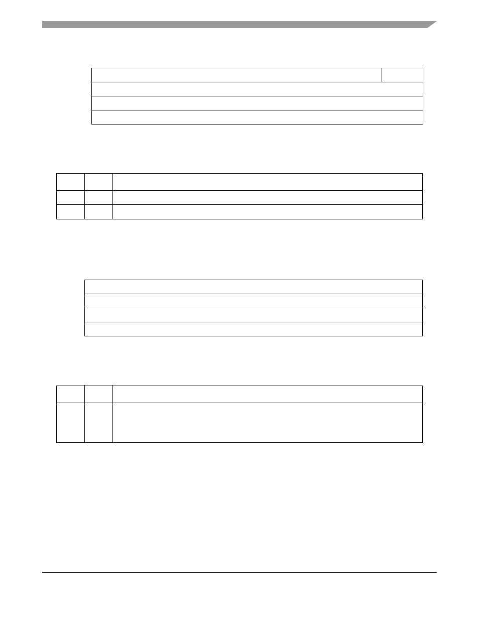
Figure 39-7. I
2
C Address Register (I2ADD)
Table 39-2. I2ADD Field Descriptions
Bits
Name
Description
0–6
SAD
Slave address 0–6. Holds the slave address for the I
2
C port.
7
—
Reserved and should be cleared.
0
7
Field
DIV
Reset
1111_1111
R/W
R/W
Addr
Figure 39-8. I
2
C Baud Rate Generator Register (I2BRG)
Table 39-3. I2BRG Field Descriptions
Bits
Name
Description
0–7
DIV
Division ratio 0–7. Specifies the divide ratio of the BRG divider in the I
2
C clock generator. The output
of the prescaler is divided by 2 * ([DIV0–DIV7] + 3 + (2 * I2MOD[FLT])) and the clock has a 50% duty
cycle. DIV must be programmed to a minimum value of 3 if the digital filter is disabled
(I2MOD[FLT] = 0) and 6 if it is enabled (I2MOD[FLT] = 1) .