8 risc time-stamp control register (rtscr), Table 14-4. rtscr field descriptions, 9 risc time-stamp register (rtsr) – Freescale Semiconductor MPC8260 User Manual
Page 559: Risc time-stamp control register (rtscr) -11, Risc time-stamp register (rtsr) -11, Rtscr field descriptions -11
Communications Processor Module Overview
MPC8260 PowerQUICC II Family Reference Manual, Rev. 2
Freescale Semiconductor
14-11
14.3.8
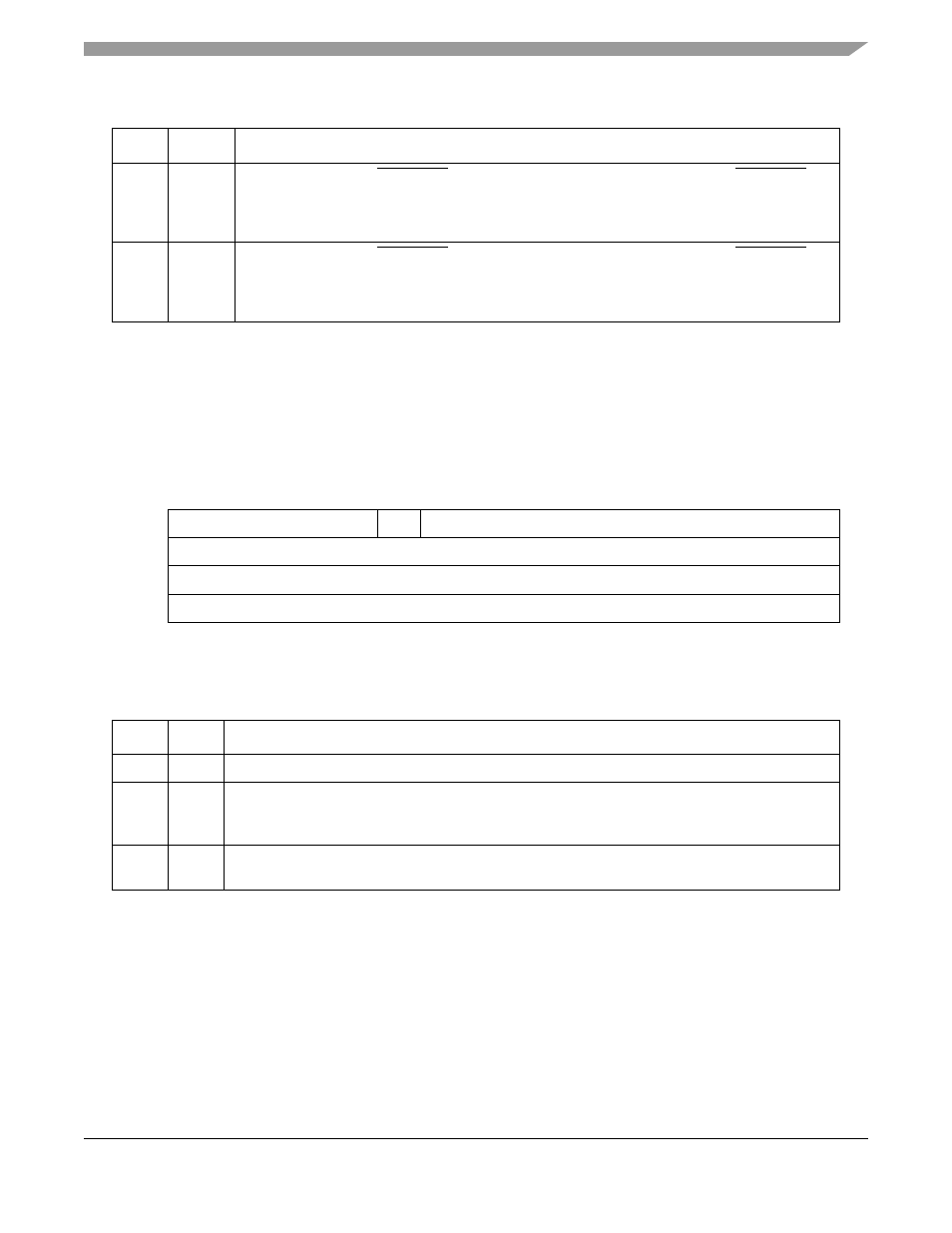
RISC Time-Stamp Control Register (RTSCR)
The RISC time-stamp control register (RTSCR), shown in
, configures the RISC time-stamp
timer (RTSR). The time-stamp timer is used by the ATM and the HDLC controllers. For application
examples, see
Section 30.5.3, “ABR Flow Control Setup,”
and
Section 36.6, “HDLC Mode Register
describes RTSCR fields.
14.3.9
RISC Time-Stamp Register (RTSR)
The RISC time-stamp register (RTSR), shown in
, contains the time stamp.
28
DEM12
Edge detect mode for DONE[1, 2] for IDMA[1, 2]. See
.” DONE[1, 2]
asserts as follows:
0 High-to-low change
1 Low-to-high change
29
DEM34
Edge detect mode for DONE[3, 4] for IDMA[3, 4]. See
.” DONE[3, 4]
asserts as follows:
0 High-to-low change
1 Low-to-high change
0
4
5
6
15
Field
—
RTE
RTPS (Timer Prescale)
Reset
0000_0000_0000_0000
R/W
R/W
Addr
Figure 14-4. RISC Time-Stamp Control Register (RTSCR)
Table 14-4. RTSCR Field Descriptions
Bits Name
Description
0–4
—
Reserved
5
RTE
Time stamp enable.
0 Disable time-stamp timer.
1 Enable time-stamp timer.
6–15
RTPS
Time-stamp timer pre-scale. Must be programmed to generate a 1-µs period input clock to the
time-stamp timer. (Time-stamp frequency = (CPM frequency)/(RTPS+2)
Table 14-3. RISC Controller Configuration Register Field Descriptions (continued)
Bits
Name Description