1 precharge-to-activate interval, Figure 11-20. pretoact = 2 (2 clock cycles), 2 activate to read/write interval – Freescale Semiconductor MPC8260 User Manual
Page 457: Precharge-to-activate interval -39, Activate to read/write interval -39, Pretoact = 2 (2 clock cycles) -39, Section 11.4.6.1, “precharge-to-activate interval, Section 11.4.6.2, “activate to read/write interval, Section 11.4.6.1, Precharge-to-activate interval
Memory Controller
MPC8260 PowerQUICC II Family Reference Manual, Rev. 2
Freescale Semiconductor
11-39
•
Last data out to precharge (P/LSDMR[LDOTOPRE]).
Section 11.4.6.4, “Last Data Out to
•
Write recovery, last data in to precharge (P/LSDMR[WRC]). See
Section 11.4.6.5, “Last Data In
•
Refresh recovery interval (P/LSDMR[RFRC]). See
Section 11.4.6.6, “Refresh Recovery Interval
•
External address multiplexing present (P/LSDMR[EAMUX]). See
•
External buffers on the control lines present (P/LSDMR[BUFCMD]). See
“External Address and Command Buffers (BUFCMD).”
The following sections describe the SDRAM parameters that are programmed in the P/LSDMR register.
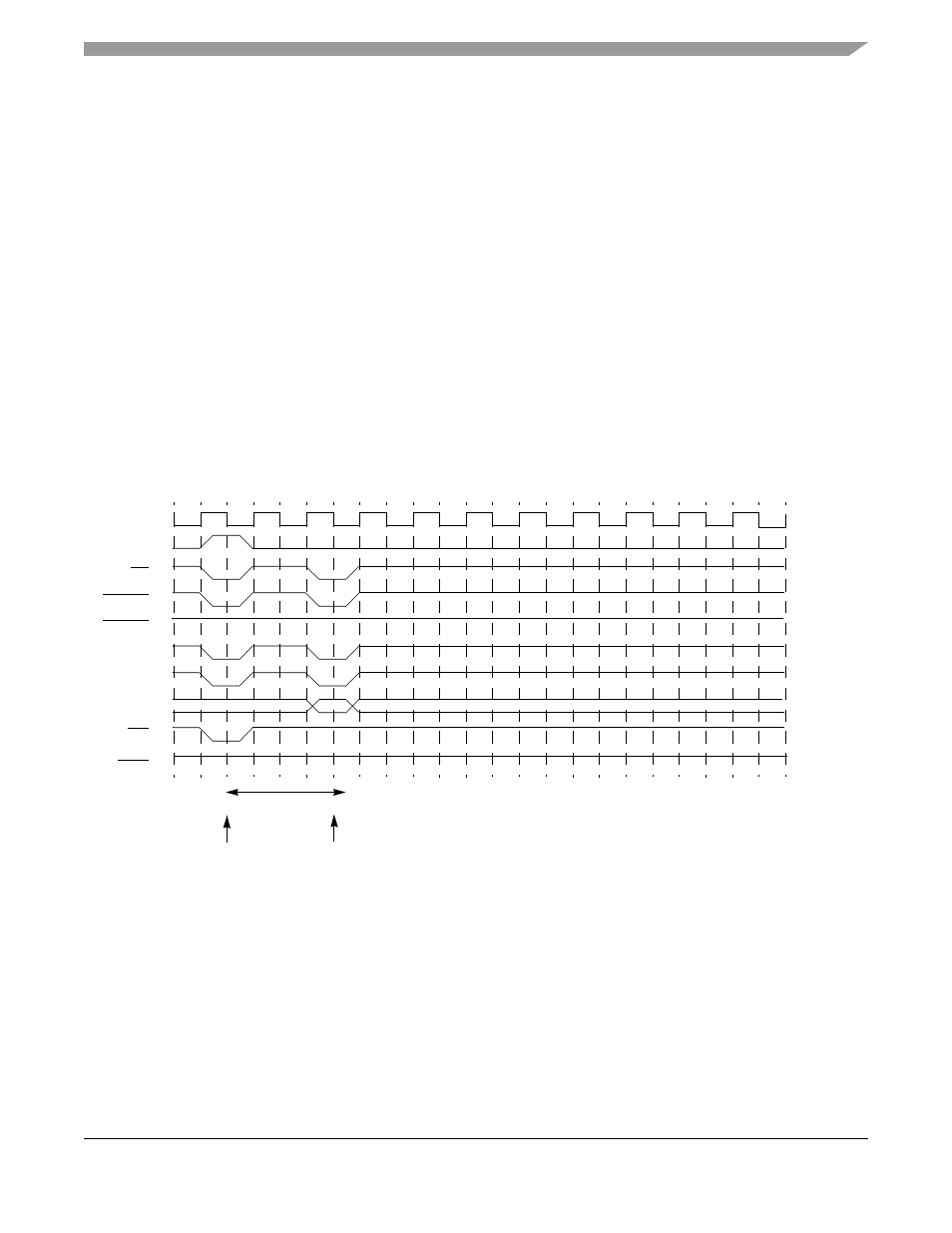
11.4.6.1
Precharge-to-Activate Interval
, this parameter, controlled by P/LSDMR[PRETOACT] defines the
earliest timing for activate or refresh command after a precharge command.
Figure 11-20. PRETOACT = 2 (2 Clock Cycles)
11.4.6.2
Activate to Read/Write Interval
As represented in
, this parameter, controlled by P/LSDMR[ACTTORW], defines the earliest
timing for
READ
/
WRITE
command after an
ACTIVATE
command.
CLK
ALE
CS
SDRAS
SDCAS
WE
DQM
PRECHARGE
Command
ACTIVATE
MA11
MA10
MA[0–9]
RAy
RAy
Bank A
Command
Bank A
PRETOACT = 2