Figure 1-5. lan-to-wan bridge router configuration, 4 cellular base station, Figure 1-6. cellular base station configuration – Freescale Semiconductor MPC8260 User Manual
Page 111: Cellular base station -17, Lan-to-wan bridge router configuration -17, Cellular base station configuration -17, Section 1.7.1.4, “cellular base station, Figure 1-5
Overview
MPC8260 PowerQUICC II Family Reference Manual, Rev. 2
Freescale Semiconductor
1-17
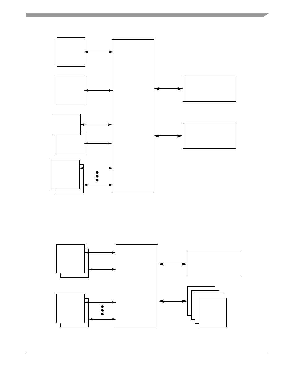
Figure 1-5. LAN-to-WAN Bridge Router Configuration
1.7.1.4
Cellular Base Station
shows a cellular base station configuration (refer to note at the beginning of
).
Figure 1-6. Cellular Base Station Configuration
PowerQUICC II
60x Bus
SDRAM/DRAM/SRAM
Local Bus
SDRAM/DRAM/SRAM
ATM Connection
Tables (optional)
MII
Transceiver
10/100BaseT
155 Mbps
PHY
ATM
Data
SMC/I2C/SPI/SCC
Slow
Comm
PHY
UTOPIA Multi PHY
10/100BaseT
or
MII
Transceiver
155 Mbps
PHY
ATM
UTOPIA Multi PHY
PowerQUICC II
60x Bus
SDRAM/DRAM/SRAM
Channelized Data
(up to 256 channels)
DSP Bank
on
Local
Bus
Local Bus
TDM0
Slaves
SMC/I2C/SPI/SCC
Slow
Comm
PHY
Framer
TDM1