Figure 25-2. ethernet block diagram, 2 features, Features -2 – Freescale Semiconductor MPC8260 User Manual
Page 786: Ethernet block diagram -2
SCC Ethernet Mode
MPC8260 PowerQUICC II Family Reference Manual, Rev. 2
25-2
Freescale Semiconductor
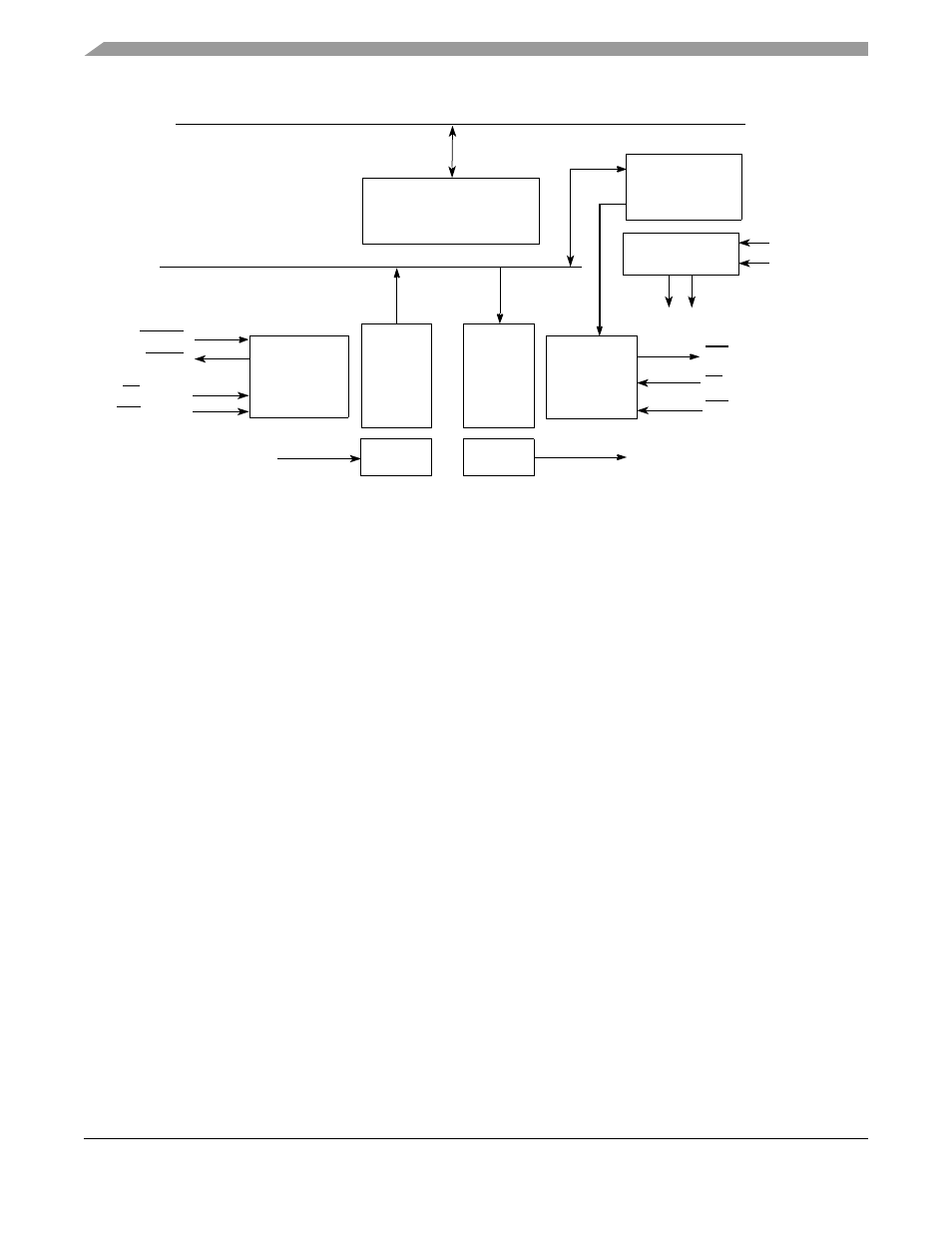
Figure 25-2. Ethernet Block Diagram
The PowerQUICC II Ethernet controller requires an external serial interface adaptor (SIA) and transceiver
function to complete the interface to the media.
Although the PowerQUICC II contains DPLLs that allow Manchester encoding and decoding, these
DPLLs were not designed for Ethernet rates. Therefore, the PowerQUICC II Ethernet controller bypasses
the on-chip DPLLs and uses the external system interface adaptor on the EEST instead. The on-chip DPLL
cannot be used for low-speed (1-Mbps) Ethernet either because it cannot properly detect start-of-frame or
end-of-frame.
Note that the CPM of the PowerQUICC II requires a minimum system clock frequency of 24 MHz to
support Ethernet.
25.2
Features
The following list summarizes the main features of the SCC in Ethernet mode:
•
Performs MAC layer functions of Ethernet and IEEE 802.3
•
Performs framing functions
— Preamble generation and stripping
— Destination address checking
— CRC generation and checking
— Automatically pads short frames on transmit
— Framing error (dribbling bits) handling
•
Full collision support
— Enforces the collision (jamming)
— Truncated binary exponential backoff algorithm for random wait
Shifter
Rx
Receiver
Control
Unit
FIFO
Shifter
Tx
Transmitter
Control
Unit
FIFO
Slot Time
Clock
Generator
Internal Clocks
Control
Registers
TXD
RXD
Peripheral Bus
Data
Data
RCLK
TCLK
and Defer
Counter
RTS = TENA
Random
N
o.
CD = RENA
CTS = CLSN
CTS = CLSN
CD = RENA
REJECT
RSTRT
60x Bus