1 utopia slave multiple phy operation, 2 utopia clocking modes, 3 utopia loop-back modes – Freescale Semiconductor MPC8260 User Manual
Page 1007: Table 30-46. utopia loop-back modes, 13 atm registers, Utopia slave multiple phy operation -87, Utopia clocking modes -87, Utopia loop-back modes -87, Atm registers -87
ATM Controller and AAL0, AAL1, and AAL5
MPC8260 PowerQUICC II Family Reference Manual, Rev. 2
Freescale Semiconductor
30-87
30.12.2.1 UTOPIA Slave Multiple PHY Operation
The user should write the ATM controller PHY address in FPSMR[PHY ID].
30.12.2.2 UTOPIA Clocking Modes
The UTOPIA clock can be generated internally or externally. If the UTOPIA clock is to be generated
internally, the user should assign one of the baud-rate generators to supply the UTOPIA clock. See
Chapter 16, “CPM Multiplexing.”
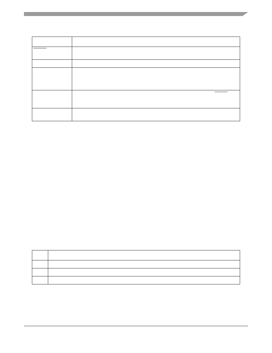
30.12.2.3 UTOPIA Loop-Back Modes
The UTOPIA interface supports loop-back mode. In this mode, the Rx and Tx UTOPIA signals are shorted
internally. Output pins are driven; input pins are ignored.
Note that in loop-back mode, the transmitter and receiver must operate in complementary modes. For
example, if the transmitter is master, the receiver must be a slave (FPSMR[TUMS] = 0, FPSMR[RUMS]
= 1).
Modes are selected through GFMR[DIAG], as shown in
30.13 ATM Registers
The following sections describe the configuration of the registers in ATM mode.
RxENB
Receive enable. Asserted by the master device to signal the slave to sample the RxDATA and
RxSOC signals.
RxCLAV
Receive cell available. Asserted by the ATM controller to indicate it can receive a complete cell.
RxPRTY
Receive parity. Asserted by the PHY device. It is an odd parity bit over the RxDATA[15–0]. If
there is a RxPRTY error and the receive parity check FPSMR[RxP] is cleared, the cell is
discarded. See
Section 30.13.2, “FCC Protocol-Specific Mode Register (FPSMR)
,” and
Section 30.10.7, “UNI Statistics Table
.”
RxCLK
Receive clock. Provides the synchronization reference for the RxDATA, RxSOC, RxENB,
RxCLAV, and RxPRTY signals. All the above signals are sampled at low-to-high transitions of
RxCLK.
RxADD[4–0]
Receive address. Address bus from master to the ATM controller device used to select the
appropriate M-PHY device.
Table 30-46. UTOPIA Loop-Back Modes
DIAG
Description
00
Normal mode
01
Loop-back. UTOPIA Rx and Tx signals are shorted internally. Output pins are driven, input pins are ignored.
1x
Reserved
Table 30-45. UTOPIA Slave Mode Signals (continued)
Signal
Description