3 aal0 protocol-specific tct, Figure 30-33. aal0 protocol-specific tct, Table 30-24. aal0-specific tct field descriptions – Freescale Semiconductor MPC8260 User Manual
Page 977: 4 aal1 ces protocol-specific tct, 5 aal2 protocol-specific tct, 6 vbr protocol-specific tcte, Aal0 protocol-specific tct -57, Aal1 ces protocol-specific tct -57, Aal2 protocol-specific tct -57, Vbr protocol-specific tcte -57
ATM Controller and AAL0, AAL1, and AAL5
MPC8260 PowerQUICC II Family Reference Manual, Rev. 2
Freescale Semiconductor
30-57
30.10.2.3.3
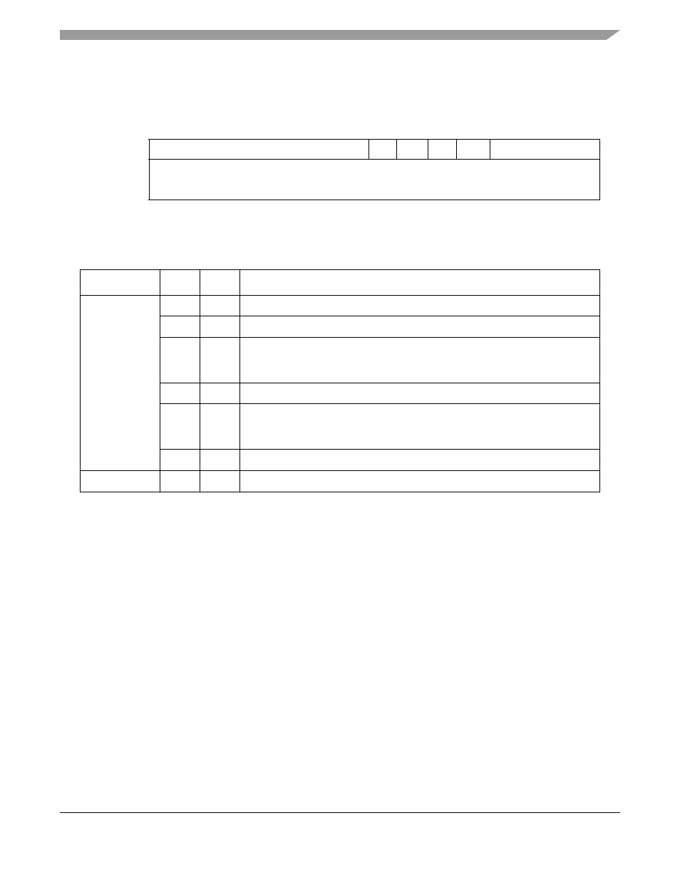
AAL0 Protocol-Specific TCT
shows the AAL0 protocol-specific TCT.
describes AAL0 protocol-specific TCT fields.
30.10.2.3.4
AAL1 CES Protocol-Specific TCT
Refer to
Section 31.9.2.1, “AAL1 CES Protocol-Specific TCT.”
30.10.2.3.5
AAL2 Protocol-Specific TCT
Refer to
Section 32.3.5.1, “AAL2 Protocol-Specific TCT.”
30.10.2.3.6
VBR Protocol-Specific TCTE
shows the VBR protocol-specific TCTE.
0
7
8
9
10
11
12
15
Offset + 0x10
—
0
CR10
—
ACHC
—
Offset + 0x12
—
Offset + 0x14
Figure 30-33. AAL0 Protocol-Specific TCT
Table 30-24. AAL0-Specific TCT Field Descriptions
Offset
Bits
Name
Description
0x10
0–7
—
Reserved, should be cleared.
8
0
Must be 0.
9
CR10
CRC-10
0 CRC10 insertion is disabled.
1 CRC10 insertion is enabled.
10
—
Reserved, should be cleared.
11
ACHC
ATM cell header change
0 Normal operation ATM cell header is taken from AAL0 buffer.
1 VPI/VCI (28 bits) are taken from TCT.
12–15
—
Reserved, should be cleared.
0x12–0x14
—
—
Reserved, should be cleared.