Table 4-18. l_tescr2 field descriptions, L_tescr2 field descriptions -43 – Freescale Semiconductor MPC8260 User Manual
Page 215
System Interface Unit (SIU)
MPC8260 PowerQUICC II Family Reference Manual, Rev. 2
Freescale Semiconductor
4-43
4.3.2.13
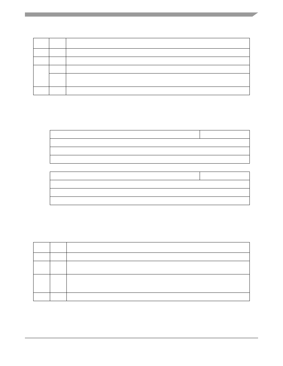
Local Bus Transfer Error Status and Control Register 2 (L_TESCR2)
The local bus transfer error status and control register 2 (L_TESCR2) is shown in
describes L_TESCR2 fields.
17
DMD
Data errors disable. Setting this bit disables parity errors on the local bus.
18–19
—
Reserved, should be cleared.
20
—
.29
µm (HiP3) Rev A.1 silicon: reserved, should be cleared.
DER
.29
µm (HiP3) Rev B.3 silicon and forward: Data error. Set when a core machine check is asserted
due to parity errors in the local bus.
21–31
—
Reserved, should be cleared.
0
11
12
15
Field
—
PB
Reset
0000_0000_0000_0000
R/W
R/W
Addr
16
27
28
31
Field
BNK
—
Reset
0000_0000_0000_0000
R/W
R/W
Addr
0x1004E
Note: all bits are status bits and are cleared by writing 1s.
Figure 4-34. Local Bus Transfer Error Status and Control Register 2 (L_TESCR2)
Table 4-18. L_TESCR2 Field Descriptions
Bits
Name
Description
0–11
—
Reserved, should be cleared.
12–15
PB
Parity error on byte. There are four parity error status bits, one per 8-bit lane. A bit is set for the byte
that had a parity error.
16–27
BNK
Memory controller bank. There are twelve error status bits, one per memory controller bank. A bit is
set for the local bus memory controller bank that had an error. Note that BNK is invalid if the error
was not caused by ECC or PARITY checks.
28–31
—
Reserved, should be cleared.
Table 4-17. L_TESCR1 Field Descriptions (continued)
Bits
Name
Description