Freescale Semiconductor MPC8260 User Manual
Page 868
Multi-Channel Controllers (MCCs)
MPC8260 PowerQUICC II Family Reference Manual, Rev. 2
28-20
Freescale Semiconductor
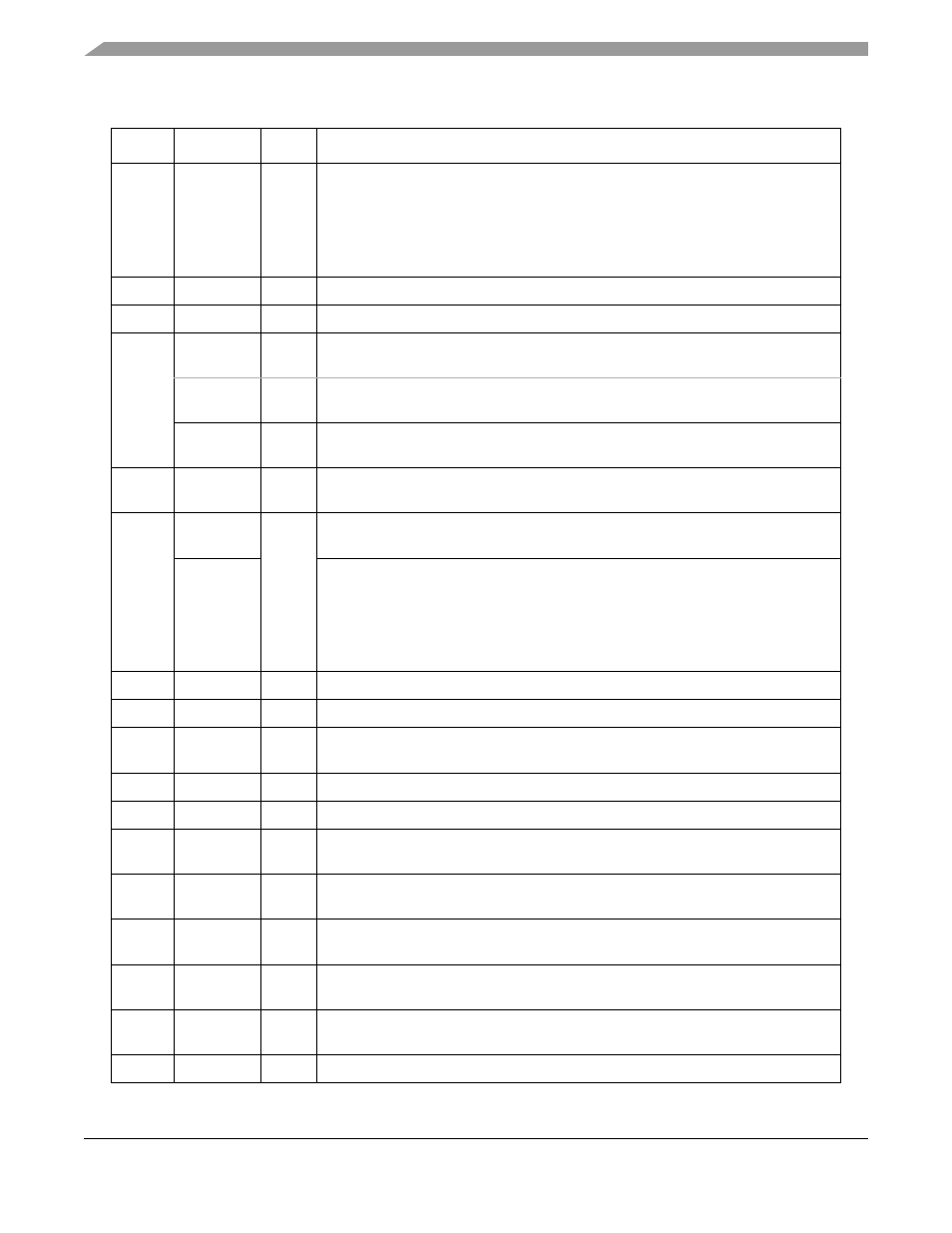
0x38
MFLR
Hword
Maximum frame length register. Defines the longest expected frame for this channel.
(64-Kbyte maximum). The remainder of a frame that is larger than MFLR is discarded
and the LG flag is set in the last frame’s BD. An interrupt request might be generated
(RXF and RXB) depending on the interrupt mask. A frame’s length is considered to
be everything between flags, including CRC. No more data is written into the current
buffer when the MFLR violation is detected.
0x3A
MAX_cnt
Hword
Max_length counter, used by the CP (read-only for the user)
0x3C
RCRC
Word
Temporary receive CRC, used by the CP (read-only for the user)
0x40
N
Hword
Applies to ITU-T/ANSI SS7 only. Interrupt threshold in octet counting mode (N=16).
See
Section 28.3.4.2, “Signal Unit Error Monitor (SUERM)—SS7 Mode
N_cnt
Hword
Applies to ITU-T/ANSI SS7 only. Temporary down counter for N (user initialized to
the value of N).
JTSTTmp
Word
Applies to Japanese SS7 only. Temporary storage for Time-Stamp Register Value.
Used by the CP to implement a 24-ms delay before sending FISU.
0x44
D
Hword
Signal unit to signal unit error ratio (SUERM parameter, user initialized to 256). See
Section 28.3.4.2, “Signal Unit Error Monitor (SUERM)—SS7 Mode
0x46
D_cnt
Hword
Applies to ITU-T/ANSI SS7 only. Temporary down-counter for D (user initialized to
the value of D). D_cnt is decremented only when receive buffers are available.
JTTDelay
Applies to Japanese SS7 only. FISU retransmission delay (specified in units of
512¨µs). According to the Japanese SS7 standard, the delay should be 24 ms and
thus JTTDelay should be programmed to 24 ms/512 µs = 46.875 (approximately 47).
Hence, the user should program JTTDelay to 0x2F and the RTSCR to generate a 1
µs time stamp period. Refer to
Section 14.3.8, “RISC Time-Stamp Control Register
0x48
Mask1
Word
Mask for SU filtering, bytes 0-3. See
28.3.4.4, “SU Filtering—SS7 Mode
0x4C
Mask2
Hword
Mask for SU filtering, byte 4. See
28.3.4.4, “SU Filtering—SS7 Mode
0x4E
SS7_OPT
Hword
SS7 configuration register. See
Section 28.3.4.3, “SS7 Configuration Register—SS7
.”
0x50
LRB1_Tmp
Word
Temporary storage, used by CP for SU filtering.
0x54
LRB2_Tmp
Hword
Temporary storage, used by CP for SU filtering.
0x56
SUERM
Hword
Signal unit error rate monitor counter (user initialized to 0). See
“Signal Unit Error Monitor (SUERM)—SS7 Mode
.”
0x58
LRB1
Word
Four first bytes of last received signal unit. Used by CP for SU filtering. See
.”
0x5C
LRB2
Hword
Fifth byte of last received signal unit. Used by CP for SU filtering. See
0x5E
T
Hword
SUERM threshold value (user initialized to 64). See
Section 28.3.4.2, “Signal Unit
Error Monitor (SUERM)—SS7 Mode
0x60
LHDR
Word
The BSN, BIB, FSN, FIB fields of last transmitted signal unit and result of CRC. Used
by CP for automatic FISU transmission.
0x64
LHDR_Tmp
Word
Temporary storage, used by CP for automatic FISU transmission.
Table 28-10. Channel-Specific Parameters for SS7 (continued)
Offset
1
Name
2
Width
Description