3 cps buffer structure, Cps buffer structure -15, Buffer structure example for cps packets -15 – Freescale Semiconductor MPC8260 User Manual
Page 1077: Section 32.3.5.3, “cps buffer structure, Figure 32-9 shows a cps txbd
ATM AAL2
MPC8260 PowerQUICC II Family Reference Manual, Rev. 2
Freescale Semiconductor
32-15
32.3.5.3
CPS Buffer Structure
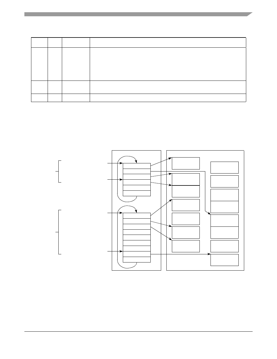
The CPS buffer structure consists of a BD table that points to data buffers. The BDs contain, apart from
the buffer pointer, also the packet header. The buffers contain the packet payload. See
.
Figure 32-8. Buffer Structure Example for CPS Packets
shows a CPS TxBD.
0x0A
—
Number of
Packets In
Queue
Counts the number of packets currently in the queue. If this queue is switched, the
receiver increments this counter with each new received packet and the transmitter
decrements it with each packet sent. For switching, the user should initialize this
counter to zero. When this queue is not switched, this counter counts down with every
packet sent. (This can have various purposes such as evaluating the packet rate that
is transmitted from this queue.).
0x0C
—
NextQueue
Points to the next TxQD to be serviced after this one. See
.”
0x0E
—
—
Reserved, should be cleared during initialization.
1
Boldfaced entries must be initialized by the user.
Table 32-2. CPS TxQD Field Descriptions (continued)
Offset
Bits
Name
1
Description
BD memory space
TxBD_Table_Base
TxBD table
of ch 1
TxBD table
of ch 4
TxBD_Table_Offset_Out
Pointers
TxBD 1
TxBD 2
TxBD 3
TxBD 4
TxBD 5
TxBD 6
TxBD 7
TxBD 8
TxBD 9
TxBD 1
TxBD 2
TxBD 3
TxBD 4
TxBD 5
TxBD 6
Tx buffer 3 of
channel 1
Tx buffer 4 of
channel 1
Tx buffer 1 of
channel 4
Tx buffer 2 of
channel 4
Tx buffer 3 of
channel 4
Tx buffer 2 of
channel 1
Tx buffer 8 of
channel 4
•
•
•
•
•
•
Tx buffer 1 of
channel 1
Data memory space
from
CPS TxQD
Pointers
from
another
CPS TxQD
TxBD_Table_Base
TxBD_Table_Offset_Out