Brocade Network Advisor SAN + IP User Manual v12.1.0 User Manual
Page 1631
Brocade Network Advisor SAN + IP User Manual
1585
53-1002949-01
Provisioning flows
44
NOTE
You can also right click on either of these objects in the products list or connectivity map and
select Fabric Vision > Flow > Add from the menu. Selected switches, switch ports, initiator,
ports, and target ports must be able to support Flow Vision.
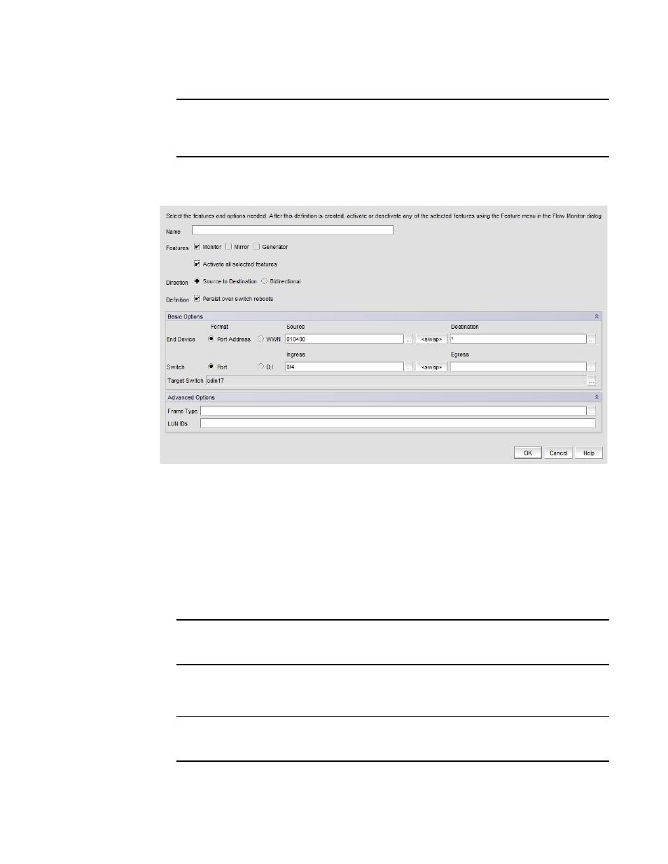
The Add Flow Definition dialog box displays. Note that you must select Advanced Options to
display the Frame Type and LUN IDs fields at the bottom of the dialog box.
FIGURE 692
Add Flow Definition dialog box
Dialog box fields will be populated with criteria and flow identifiers (such as SIDs and DIDs) for
the appropriate flow definition based on the object selected to launch dialog box. For example,
launching the dialog box from a target port will populate the dialog box with the source device
PID, ingress switch port, monitor, and destination device as *. An asterisk (*) denotes any
selected device in the same zone as the source device. Refer to
on page 1611 for details on criteria populated depending on the context from
which the dialog box was launched.
3. Enter a name for the flow using 20 alphanumeric or underscore characters.
NOTE
Use unique names for flows defined in a physical switch. Names do not have to be unique for
flows defined in logical switches.
4. Select at least one feature - Monitor, Mirror, or Generator
5. Select Activate all selected features to activate features that you have selected.
NOTE
Specific parameters for flow definitions may not be supported by some features. Refer to
parameter and configuration rules and limitations”
on page 1612 for details.
6. Select Source to Destination or Bidirectional flow.