3 memory map/register definition, 1 top level module memory map, Memory map/register definition -6 – Freescale Semiconductor MCF5480 User Manual
Page 936: Top level module memory map -6
MCF548x Reference Manual, Rev. 3
30-6
Freescale Semiconductor
.
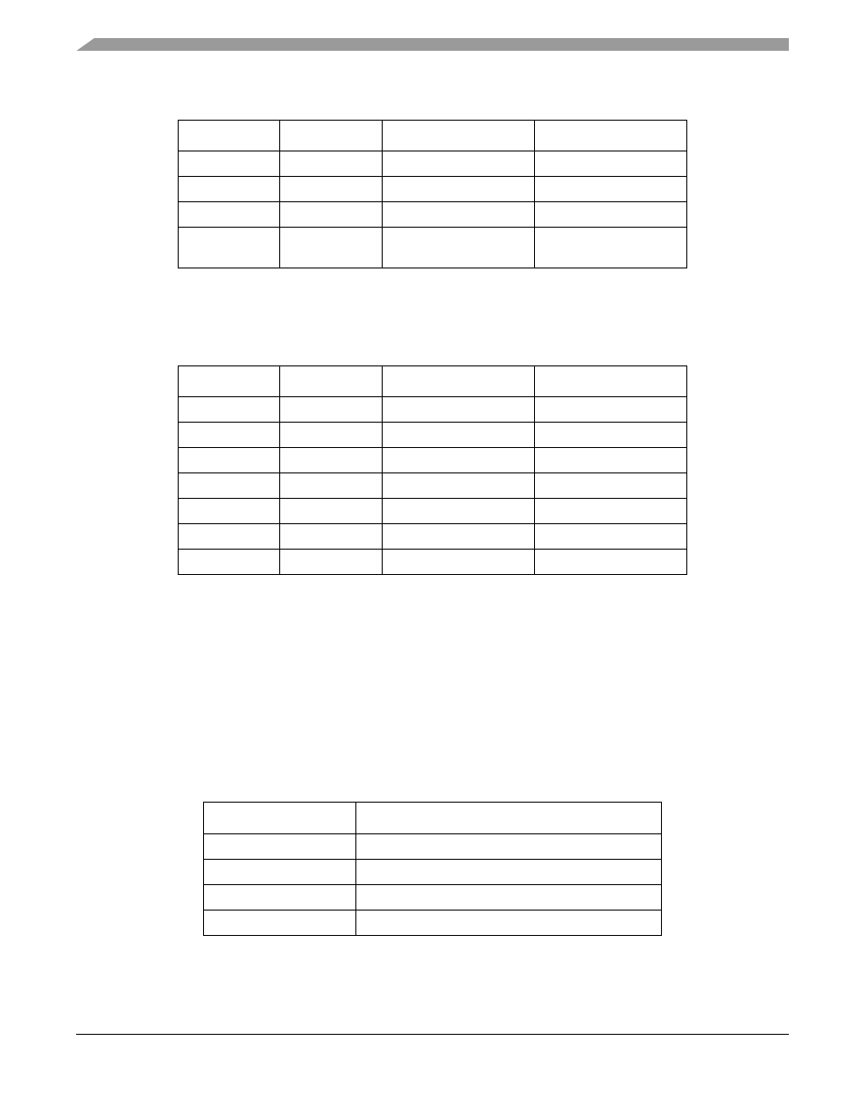
A false carrier condition occurs if the PHY detects a bad start-of-stream delimiter. This condition is
signaled to the MII by asserting EnRXER and placing 1110 on EnRXD. EnRXDV must also be
de-asserted. The valid encodings of EnRXDV, EnRXER and EnRXD[3:0] are shown in
30.3
Memory Map/Register Definition
This section gives an overview of the FEC registers. The FEC is programmed by control/status registers
(CSRs). The CSRs are used for mode control and to extract global status information.
30.3.1
Top Level Module Memory Map
The FEC implementation occupies a 1-Kbyte memory map space. This is divided into two sections of 512
bytes each. The first is used for control/status registers. The second contains event/statistic counters held
in the MIB block.
defines the top level memory map.
Table 30-2. MII: Valid Encoding of E
n
TXD, E
n
TXEN and E
n
TXER
EnTXEN
EnTXER
EnTXD[3:0]
Indication
0
0
0000 through 1111
Normal inter-frame
0
1
0000 through 1111
Reserved
1
0
0000 through 1111
Normal data transmission
1
1
0000 through 1111
Transmit error
propagation
Table 30-3. MII: Valid Encoding of E
n
RXD, E
n
RXER and E
n
RXDV
EnRXDV
EnRXER
EnRXD[3:0]
Indication
0
0
0000 through 1111
Normal inter-frame
0
1
0000
Normal inter-frame
0
1
0001 through 1101
Reserved
0
1
1110
False Carrier
0
1
1111
Reserved
1
0
0000 through 1111
Normal Data Reception
1
1
0000 through 1111
Data reception with errors
Table 30-4. Module Memory Map
Address
Function
MBAR + 0x9000–91FF
FEC 0 Control/Status Registers
MBAR + 0x9200–93FF
FEC 0 MIB Block Counters
MBAR + 0x9800–99FF
FEC 1 Control/Status Registers
MBAR + 0x9A00–9BFF
FEC 1 MIB Block Counters