2 i2c overview, 3 features, 2 external signals – Freescale Semiconductor MCF5480 User Manual
Page 856: I2c overview -2, Features -2, External signals -2, C overview
MCF548x Reference Manual, Rev. 3
28-2
Freescale Semiconductor
28.1.2
I
2
C Overview
I
2
C is a two-wire, bidirectional serial bus which provides a simple, efficient method of data exchange
between devices. This two-wire bus minimizes the interconnection between the devices.
The interface is designed to operate up to 100 kbps with maximum bus loading and timing. The device is
capable of operating at higher baud rates, up to a maximum of clock/20, with reduced bus loading. The
maximum communication length and the number of devices that can be connected are limited by a
maximum bus capacitance of 400 pF.
This bus is suitable for applications requiring occasional communications over a short distance between a
number of devices. It also provides flexibility, allowing additional devices to be connected to the bus for
further expansion and system development.
I
2
C is a true multi-master bus including collision detection and arbitration to prevent data corruption if two
or more masters attempt to control the bus simultaneously. This feature provides the capability for complex
applications with multi-processor control. It may also be used for rapid testing and alignment of end
products via external connections to an assembly-line computer.
The MCF548x contains one I
2
C interface, with a dedicated set of pins.
28.1.3
Features
The I
2
C module has the following key features:
•
Compatible with I2C bus standard
•
Multi-master operation
•
Software programmable for one of 50 different serial clock frequencies
•
Software selectable acknowledge bit
•
Interrupt driven byte-by-byte data transfer
•
Arbitration lost interrupt with automatic mode switching from master to slave
•
Calling address identification interrupt
•
Start and stop signal generation/detection
•
Repeated start signal generation
•
Acknowledge bit generation/detection
•
Bus busy detection
28.2
External Signals
The following table describes the external I
2
C signals
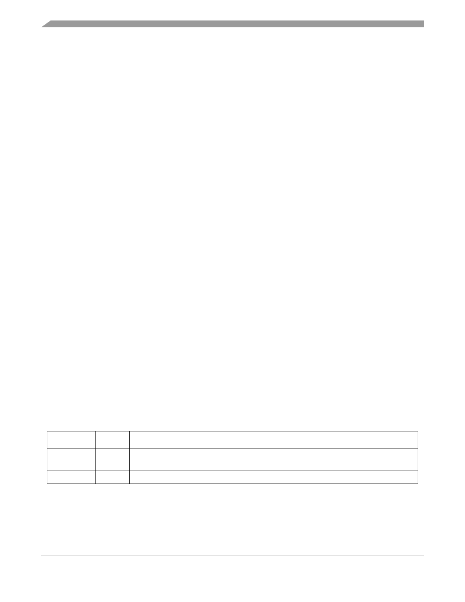
Table 28-1. I
2
C Signal Summary
Signal Name Direction
Description
SCL
I/O
Open-drain clock signal for the I
2
C interface. Either it is driven by the I
2
C module when the bus
is in the master mode, or it becomes the clock input when the I
2
C is in the slave mode.
SDA
I/O
Open-drain signal that serves as the data input/output for the I
2
C interface.