3 ethernet control register (ecr), Ethernet control register (ecr) -13 – Freescale Semiconductor MCF5480 User Manual
Page 943
Memory Map/Register Definition
MCF548x Reference Manual, Rev. 3
Freescale Semiconductor
30-13
30.3.3.3
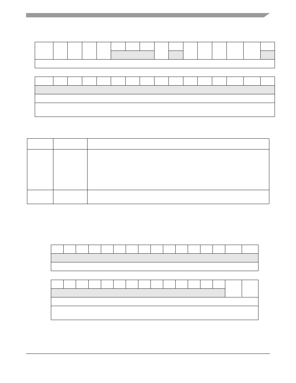
Ethernet Control Register (ECR)
ECR is a read/write user register, though both fields in this register may be altered by hardware as well.
The ECR is used to enable/disable the FEC.
31
30
29
28
27
26
25
24
23
22
21
20
19
18
17
16
R HBERR BABR BABT
GRA
TXF
0
0
0
MII
0
LC
RL
XFUN XFERR RFERR
0
W
Reset
0
0
0
0
0
0
0
0
0
0
0
0
0
0
0
0
15
14
13
12
11
10
9
8
7
6
5
4
3
2
1
0
R
0
0
0
0
0
0
0
0
0
0
0
0
0
0
0
0
W
Reset
0
0
0
0
0
0
0
0
0
0
0
0
0
0
0
0
Reg
Addr
MBAR + 0x9008 (FEC0), 0x9808 (FEC1)
Figure 30-3. Ethernet Interrupt Mask
Register (EIMR)
Table 30-8. EIMR Field Descriptions
Bits
Name
Description
31–27,
23, 21–17
and
.
Interrupt mask. Each bit corresponds to an interrupt source defined by the EIR register. The
corresponding EIMR bit determines whether an interrupt condition can generate an interrupt.
At every processor clock, the EIR samples the signal generated by the interrupting source. The
corresponding EIR bit reflects the state of the interrupt signal even if the corresponding EIMR
bit is set.
0 The corresponding interrupt source is masked.
1 The corresponding interrupt source is not masked.
26–24,
22, 16–0
—
Reserved, should be cleared.
31
30
29
28
27
26
25
24
23
22
21
20
19
18
17
16
R
0
0
0
0
0
0
0
0
0
0
0
0
0
0
0
0
W
Reset
1
1
1
1
0
0
0
0
0
0
0
0
0
0
0
0
15
14
13
12
11
10
9
8
7
6
5
4
3
2
1
0
R
0
0
0
0
0
0
0
0
0
0
0
0
0
0
ETHER
_EN
RESET
W
Reset
0
0
0
0
0
0
0
0
0
0
0
0
0
0
0
0
Reg
Addr
MBAR + 0x9024 (FEC0), 0x9824 (FEC1)
Figure 30-4. Ethernet Control Register (ECR)