2 serial interaction pulse (sip), 8 fir mode, 1 data format – Freescale Semiconductor MCF5480 User Manual
Page 804: Serial interaction pulse (sip) -42, Fir mode -42, Data format -42
MCF548x Reference Manual, Rev. 3
26-42
Freescale Semiconductor
The STA represents the start of the frame and the STO represents the end of the frame. Both of STA and
STO are defined as 01111110 in binary format. In the transmitted data and FCS, a 0 is inserted after 5
consecutive 1s. The FCS is a 16-bit CRC defined as:
Eqn. 26-3
26.4.7.2
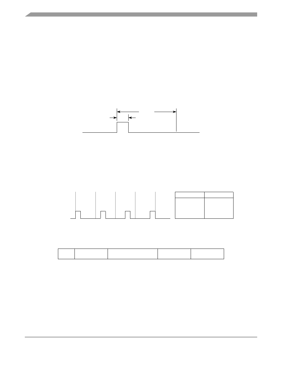
Serial Interaction Pulse (SIP)
The MIR and FIR system must emit SIP at least once per 500ms while the connection lasts, in order to
inform slower systems (SIR) not to interfere with the link. If the SIPEN bit in IRCR1 is high, the
transmitter automatically appends one SIP after every frame. SIP also can be sent by writing 1 to SIPREQ
bit in IRCR2. If SIPREQ is high and the transmitter is in an idle state, one SIP is sent and the SIPREQ bit
illustrates how SIP is defined.
Figure 26-38. Serial Interaction Pulse (SIP)
26.4.8
FIR Mode
26.4.8.1
Data Format
The data field is 4 PPM encoded by the transmitter. Data encoding is done LSB first. Each chip duration
is 125 ns.
Figure 26-39. Data Format in FIR Mode
shows the packet format.
The preamble (PA) field is used by a receiver to establish phase lock. After receiving the start flag (STA),
the receiver begins to interpret the 4 PPM encoded symbols. The receiver continues receiving until it
receives the stop flag (STO). The FCS is a 32-bit CRC defined as:
Eqn. 26-4
The chip patterns for PA, STA, and STO are defined in
.
Figure 26-40. FIR Mode Packet Format
PA
STA
DATA
FCS
STO
CRC x
( )
x
16
x
12
x
5
1
+
+
+
=
1.6 µs
8.7 µs
Binary Data
0
0
0
1
1
0
1
1
Bit Pair
4 PPM Data
00
1000
01
0100
10
0010
11
0001
CRC x
( )
x
32
x
26
x
23
x
22
x
16
x
12
x
11
x
10
+
+
+
+
+
+
+
x
8
x
7
x
5
x
4
+
+
+
+
x
2
x 1
+
+ +
=