Table 22-35 describes aesu stat us register fields – Freescale Semiconductor MCF5480 User Manual
Page 654
MCF548x Reference Manual, Rev. 3
22-52
Freescale Semiconductor
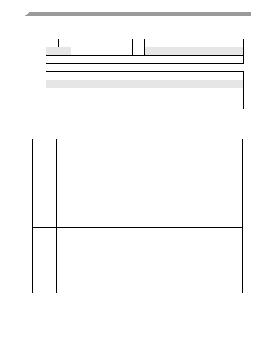
Figure 22-37. AESU Status Register (AESSR)
describes AESU status register fields.
31
30
29
28
27
26
25
24
23
22
21
20
19
18
17
16
R
0
0
HALT IFW
OFR
IE
ID
RD
0
0
0
0
0
0
0
0
W
Reset
0
0
0
0
0
0
0
0
0
0
0
0
0
0
0
0
15
14
13
12
11
10
9
8
7
6
5
4
3
2
1
0
R
0
0
0
0
0
0
0
0
0
0
0
0
0
0
0
0
W
Reset
0
0
0
0
0
0
0
0
0
0
0
0
0
0
0
0
Reg
Addr
MBAR + 0x32028
Table 22-35. AESSR Field Descriptions
Bits
Name
Description
31--30
—
Reserved
29
HALT
Halt. Indicates that the AESU has halted due to an error.
0 AESU not halted
1 AESU halted
Note: Because the error causing the AESU to stop operating may be masked to the
interrupt status register, the status register is used to provide a second source of
information regarding errors preventing normal operation.
28
IFW
Input FIFO Writable. The controller uses this signal to determine if the AESU can accept
the next BURST SIZE block of data.
0 AESU Input FIFO not ready
1 AESU Input FIFO ready
Note: The SEC implements flow control to allow larger than FIFO sized blocks of data to
be processed with a single key/IV. The AESU signals to the crypto-channel that a ‘burst
size’ amount of space is available in the FIFO.
27
OFR
Output FIFO Readable. The controller uses this signal to determine if the AESU can source
the next burst size block of data.
0 AESU Output FIFO not ready
1 AESU Output FIFO ready
Note: The SEC implements flow control to allow larger than FIFO sized blocks of data to
be processed with a single key/IV. The AESU signals to the crypto-channel that a “Burst
Size” amount of data is available in the FIFO.
26
IE
Interrupt Error.This status bit reflects the state of the ERROR interrupt signal, as sampled
by the controller interrupt status register (
Section 22.6.4.4, “SEC Interrupt Status Registers
”).
0 AESU is not signaling error
1 AESU is signaling error