4 functional description, Functional description -8, The i – Freescale Semiconductor MCF5480 User Manual
Page 862
MCF548x Reference Manual, Rev. 3
28-8
Freescale Semiconductor
28.4
Functional Description
The I
2
C has a simple bidirectional 2-wire bus for efficient inter-IC control. The two wires, serial data
address line (SDA) and serial clock line (SCL), carry information between the MCF548x and other devices
connected to the bus. Each device, including the MCF548x, is recognized by a unique address, and can
operate as either transmitter or receiver, depending on the function of the device. In addition to the
transmitters and receivers, devices can be considered as masters or slaves. A master is the device that
initiates a data transfer on the bus and generates the clock signals to permit that transfer. At that time, any
device addressed is considered a slave.
7
6
5
4
3
2
1
0
R
0
0
0
0
BNBE
TE
RE
IE
W
Reset
0
0
0
1
0
0
0
1
Reg
Addr
MBAR + 0x8F20
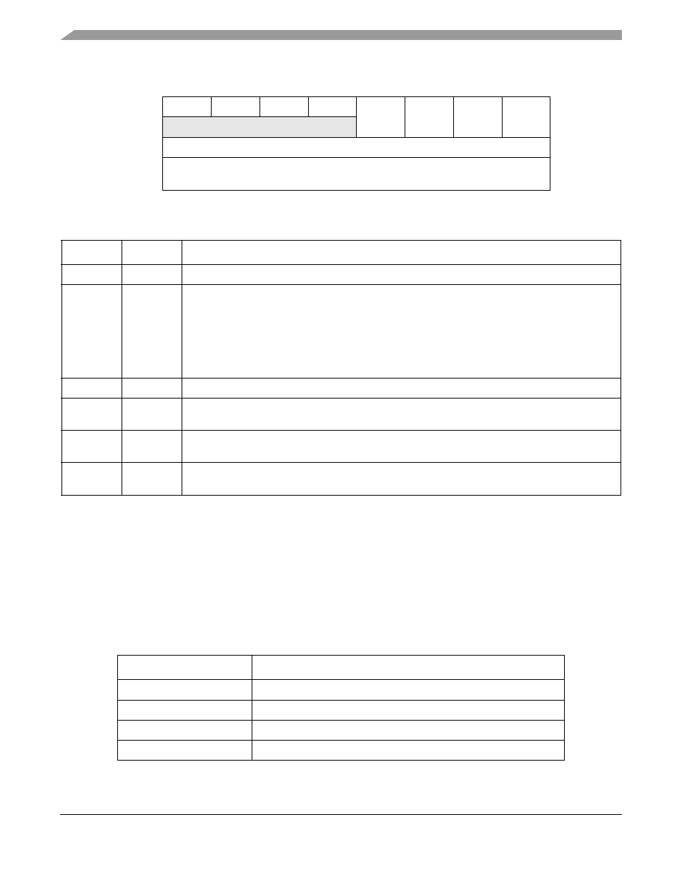
Figure 28-7. Interrupt Control Register
Table 28-8. I2ICR Field Descriptions
Bits
Name
Description
7–4
—
Reserved, should be cleared.
3
BNBE
Permits I
2
C module to generate an interrupt when the bus is NOT busy. Instead of polling the bus
busy bit to see when the bus becomes free, setting BNBE bit will cause an interrupt when a STOP
is detected on the bus. Disabling this bit will prevent these interrupts. Bus NOT busy is an IDLE
condition, therefore software must clear this bit by writing a 0 to this bit position in order to clear the
interrupt. Reset condition disables this bit.
0 Disables an interrupt when the bus is stopped
1 Enables an interrupt when the bus is stopped
5-6
—
Reserved, should be cleared.
2
TE
Routes the interrupt for the I
2
C module to the TX requestor at the multichannel DMA. Reset
condition disables this bit. Clear by writing a 0 to this bit position
1
RE
Routes the interrupt for the I
2
C module to the RX requestor at the multichannel DMA. Reset
condition disables this bit. Clear by writing a 0 to this bit position.
0
IE
Routes the interrupt for the I
2
C module to the CPU. Reset condition enables this bit. Clear by writing
a 0 to this bit position
Table 28-9. I
2
C Terminology
Term
Description
Transmitter
Device that sends the data to the bus
Receiver
Device that receives the data from the bus
Master
Device that initiates transfer, generates SCL and terminates transfer
Slave
Device that is addressed by the master