1 start and stop of dspi transfers, Start and stop of dspi transfers -19, Figure 27-11 – Freescale Semiconductor MCF5480 User Manual
Page 837: Illu
Functional Description
MCF548x Reference Manual, Rev. 3
Freescale Semiconductor
27-19
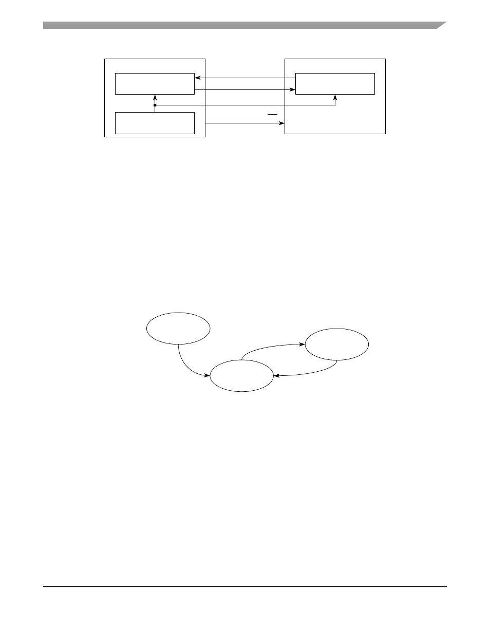
Figure 27-11. SPI Serial Protocol Overview
The DSPI has four peripheral chip select signals that are used to select which of the slaves to communicate
with: DSPICS5, DSPICS3, DSPICS1, and DSPICS0.
The transfer rate and delay settings are described in section
Section 27.7.3, “DSPI Baud Rate and Clock
27.7.1
Start and Stop of DSPI Transfers
The DSPI has two operating states; stopped and running. The states are independent of DSPI
configuration. The default state of the DSPI is stopped. In the stopped state, no serial transfers are initiated
in master mode and no transfers are responded to in slave mode. The stopped state is also a safe state for
writing the various configuration registers of the DSPI without causing undetermined results. The
DSR[TXRXS] bit is cleared in this state. In the running state, serial transfers take place. The
DSR[TXRXS] bit is set in the running state.
shows a state diagram of the start and stop
mechanism. The transitions are described in
Table 27-14
.
Figure 27-12. DSPI Start and Stop State Diagram
DSPI Master
Shift Register
Baud Rate Generator
DSPI Slave
Shift Register
SOUT
DSPISIN
DSPISOUT
SIN
DSPISCK
SCK
DSPICSn
SS
Running
TXRXS=1
Stopped
TXRXS=0
Reset
Power-On-Reset
0
1
2