3 aesu status register (aessr), Aesu status register (aessr) -51, P. 22-51 – Freescale Semiconductor MCF5480 User Manual
Page 653
Advanced Encryption Standard Execution Units (AESU)
MCF548x Reference Manual, Rev. 3
Freescale Semiconductor
22-51
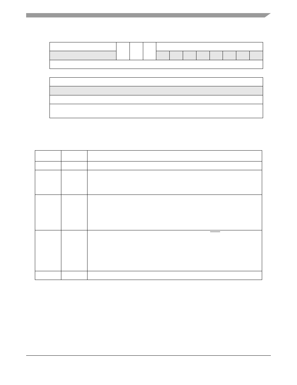
Figure 22-36. AESU Reset Control Register (AESRCR)
describes AESU reset control register fields.
22.12.3 AESU Status Register (AESSR)
The AESU status register is a read-only register that reflects the state of six status outputs. Writing to this
location will result in an address error being reflected in the AESU interrupt status register.
31
30
29
28
27
26
25
24
23
22
21
20
19
18
17
16
R
0
0
0
0
0
RI
MI
SR
0
0
0
0
0
0
0
0
W
Reset
0
0
0
0
0
0
0
0
0
0
0
0
0
0
0
0
15
14
13
12
11
10
9
8
7
6
5
4
3
2
1
0
R
0
0
0
0
0
0
0
0
0
0
0
0
0
0
0
0
W
Reset
0
0
0
0
0
0
0
0
0
0
0
0
0
0
0
0
Reg
Addr
MBAR + 0x32018
Table 22-34. AESRCR Field Descriptions
Bits
Names
Description
31–27
—
Reserved
26
RI
Reset Interrupt. Writing this bit active high causes AESU interrupts signalling DONE and
ERROR to be reset. It further resets the state of the AESU interrupt status register.
0 Don’t reset
1 Reset interrupt logic
25
MI
Module initialization is nearly the same as software reset, except that the interrupt control
register remains unchanged. This module initialization includes execution of an
initialization routine, completion of which is indicated by the RD bit in the AESU status
register
0 Don’t reset
1 Reset most of AESU
24
SR
Software reset is functionally equivalent to hardware reset (the RSTI pin), but only for
AESU. All registers and internal state are returned to their defined reset state. After the
reset completes, the AESU will enter a routine to perform proper initialization of the
parameter memories. The RD bit in the AESU status register will indicate when this
initialization routine is complete
0 Don’t reset
1 Full AESU reset
23–0
—
Reserved