2 pll, 1 pll memory map/register descriptions, 2 system pll control register (spcr) – Freescale Semiconductor MCF5480 User Manual
Page 327: Pll -5, Pll memory map/register descriptions -5, System pll control register (spcr) -5, Table 10-2/10-5, Table 10-3/10-5
PLL
MCF548x Reference Manual, Rev. 3
Freescale Semiconductor
10-5
10.2
PLL
10.2.1
PLL Memory Map/Register Descriptions
10.2.2
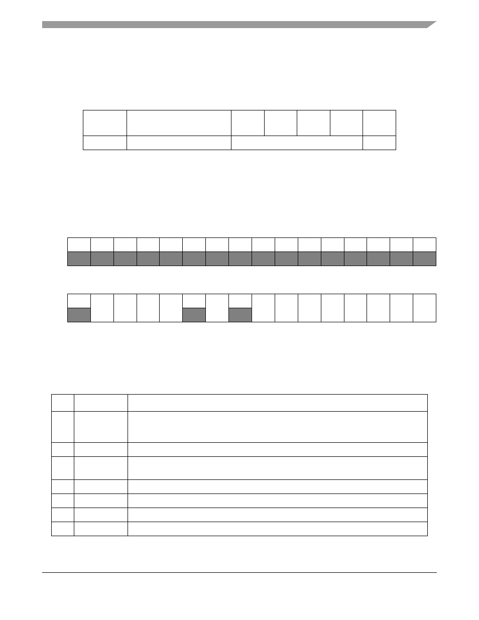
System PLL Control Register (SPCR)
The system PLL control register (SPCR) defines the clock enables used to control clocks to a set of
peripherals. Unused peripherals can have their clock stopped, reducing power consumption. In addition,
the SPCR contains a read-only bit for the system PLL lock status. At reset, the clock enables are set,
enabling all system PLL gated output clocks.
Table 10-2. System PLL Memory Map
MBAR
Offset
Name
Byte0
Byte1
Byte2
Byte3
Access
0x300
System PLL Control Register
SPCR
R/W
31
30
29
28
27
26
25
24
23
22
21
20
19
18
17
16
R
PLLK
0
0
0
0
0
0
0
0
0
0
0
0
0
0
0
W
Reset
1
0
0
0
0
0
0
0
0
0
0
0
0
0
0
0
15
14
13
12
11
10
9
8
7
6
5
4
3
2
1
0
R
0
COR
EN
CRY
ENB
CRY
ENA
CAN1
EN
0
PSC
EN
0
USB
EN
FEC1
EN
FEC0
EN
DMA
EN
CAN0
EN
FB
EN
PCI
EN
MEM
EN
W
Reset
0
1
1
1
1
1
1
1
1
1
1
1
1
1
1
1
Reg
Addr
MBAR + 0x300
Figure 10-4. System PLL Control Register (SPCR)
Table 10-3. SPCR Field Descriptions
Bits
Name Description
31
PLLK
System PLL Lock Status - Read-only lock status of the system PLL.
1 PLL has obtained frequency lock
0 PLL has not locked
30-15
—
Reserved, should be cleared.
14
COREN
Core & Communications Sub-System Clock Enable - Controls clocks for the CF4 Core, System
SRAM, CommBus Arbiter, I2C, Comm Timers, and External DMA modules
13
CRYENB
Crypto Clock Enable B - Controls the fast clock to the SEC
12
CRYENA
Crypto Clock Enable A - Controls the slow clock to the SEC
11
CAN1EN
CAN1 Clock Enable
10
—
Reserved, should be cleared.