Sor clock cycles, Table 8-2, Shows the pstdda – Freescale Semiconductor MCF5480 User Manual
Page 254
MCF548x Reference Manual, Rev. 3
8-4
Freescale Semiconductor
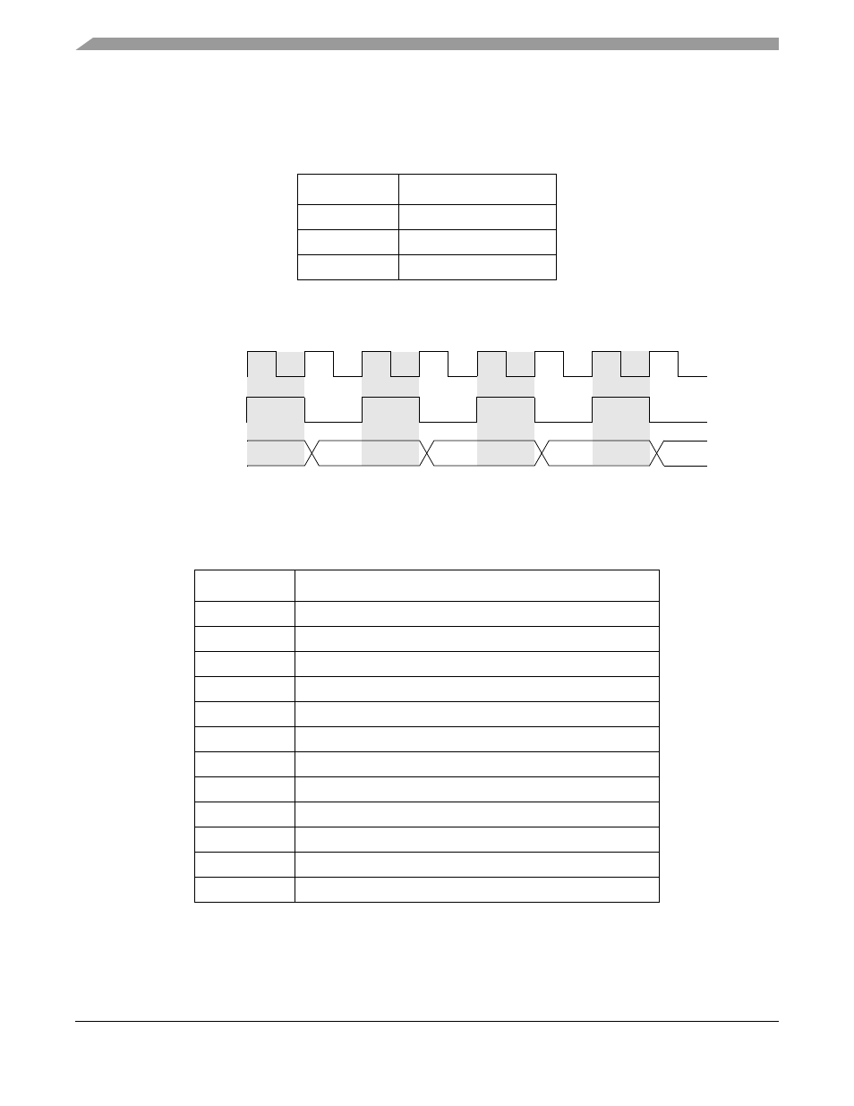
output for the processor’s sequential execution of single-cycle instructions (A, B, C, D...). Cycle counts
are shown relative to processor frequency. These outputs indicate the current processor pipeline status and
are not related to the current bus transfer.
The signal timing for the example in
Figure 8-3. PSTDDATA: Single-Cycle Instruction Timing
shows the case where a PSTDDATA module captures a memory operand on a simple load
instruction: mov.l
Table 8-2. PSTDDATA: Sequential Execution of Single-Cycle Instructions
Cycles
PSTDDATA[7:0]
T+0, T+1
{PST for A, PST for B}
T+2, T+3
{PST for C, PST for D}
T+4, T+5
{PST for E, PST for F}
Table 8-3. PSTDDATA: Data Operand Captured
Cycle
PSTDDATA[7:0]
T
{PST for mov.l, PST marker for captured operand) = {0x1, 0xB}
T+1
{0x1, 0xB}
T+2
{Operand[3:0], Operand[7:4]}
T+3
{Operand[3:0], Operand[7:4]}
T+4
{Operand[11:8], Operand[15:12]}
T+5
{Operand[11:8], Operand[15:12]}
T+6
{Operand[19:16], Operand[23:20]}
T+7
{Operand[19:16], Operand[23:20]}
T+8
{Operand[27:24], Operand[31:28]}
T+9
{Operand[27:24], Operand[31:28]}
T+10
(PST for next instruction)
T+11
(PST for next instruction,...)
PSTDDATA
PSTCLK
{A, B}
{C, D}
{E, F}
Processor Clock
T+0
T+1
T+2
T+3
T+4
T+5
T+6