Chapter 25 comm timer module (ctm), 1 introduction, 1 block diagrams – Freescale Semiconductor MCF5480 User Manual
Page 753: Chapter 25, Comm timer module (ctm), Introduction -1, Block diagrams -1, Chapter 25, “comm timer module (ctm)
MCF548x Reference Manual, Rev. 3
Freescale Semiconductor
25-1
Chapter 25
Comm Timer Module (CTM)
25.1
Introduction
This chapter contains a detailed description of the Comm Timer Module (CTM).
25.1.1
Block Diagrams
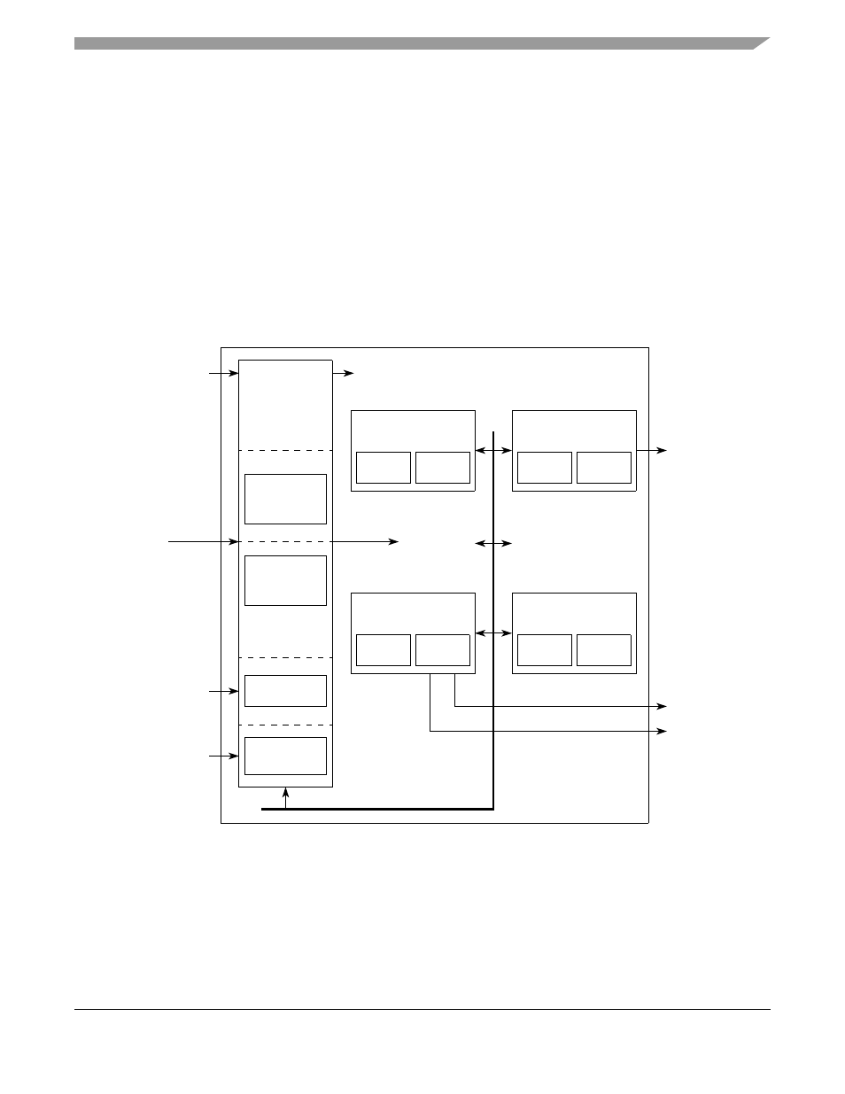
The following section presents three block diagrams showing the CTM in greater detail.
is a
high level block diagram of the CTM. The figure shows the signal flow through the sub-modules and the
architecture on a high level.
Figure 25-1. CTM High Level Block Diagram
are conceptual block diagrams of the fixed timer channel and variable timer
channel respectively. These diagrams are more detailed than earlier diagrams but should still be considered
a conceptual illustration of the actual hardware implementations.
cAcknowledge[7:0]
cInitiator
Synchronizer
Register
Timer
Variable
TimerChannel[0]
Register
Timer
Fixed
TimerChannel[0]
Write/Read
Enable
Logic
Addr
Decode
Logic
8-bit
Prescaler
externalClkIn[7:0]
clk
cAcknowledge[7:0]
Register
Timer
Variable
TimerChannel[n]
Register
Timer
Fixed
TimerChannel[n]
•
•
•
•
•
•
•
timerInterrupt
cInitiator
Comm Timer
Module
Internal Data_bus
•
•
•
•
•
•
•
Internal
Bus