Freescale Semiconductor MCF5480 User Manual
Page 769
Memory Map/Register Definition
MCF548x Reference Manual, Rev. 3
Freescale Semiconductor
26-7
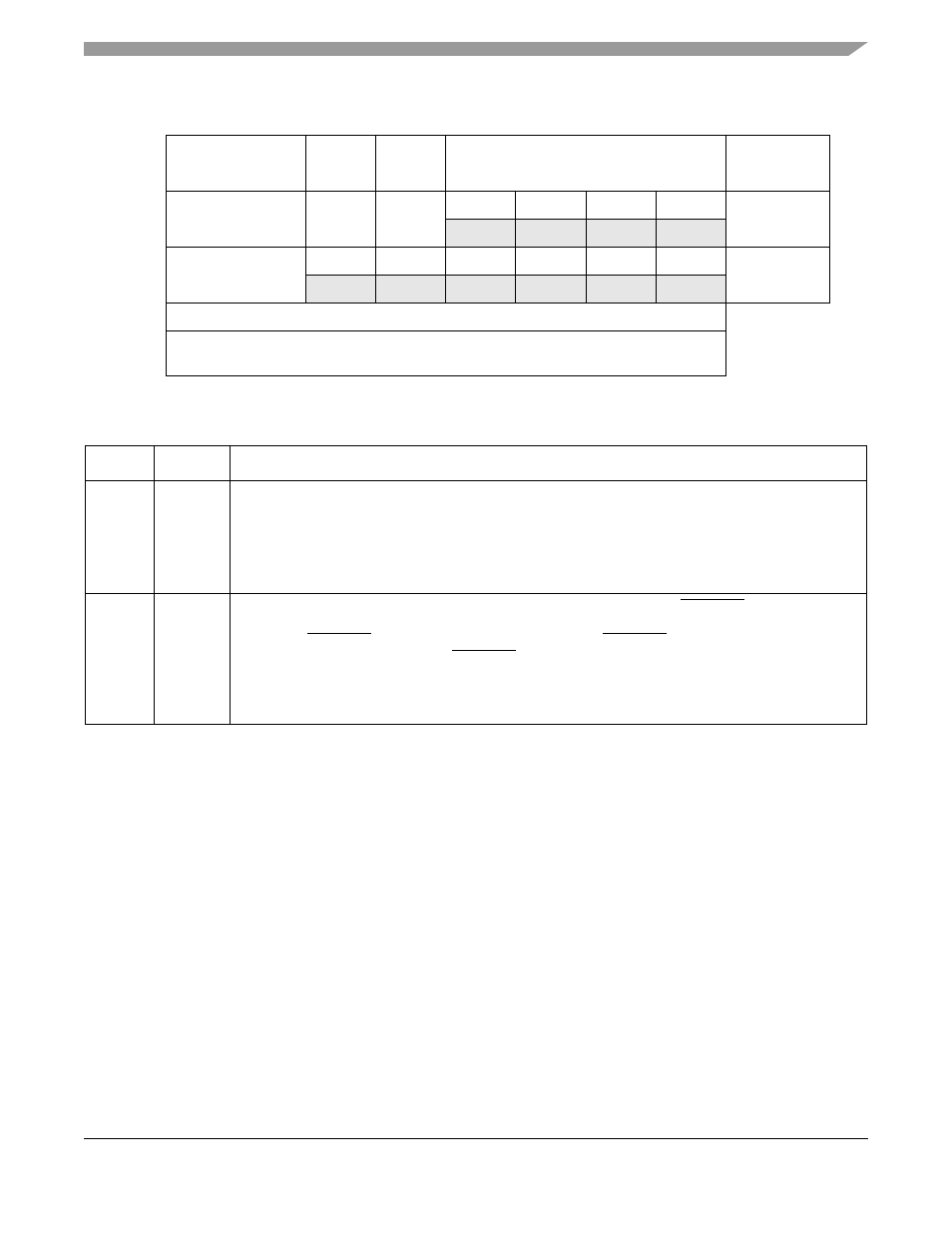
7
6
5
4
3
2
1
0
Mode
R
CM
TXRTS
TXCTS
SB
UART
W
R
CM
TXRTS
TXCTS
0
0
0
0
SIR
W
R
CM
0
0
0
0
0
0
All other modes
W
Reset
0
0
0
0
0
0
0
0
Reg
Addr
MBAR + 0x8600 (PSC0); 0x8700 (PSC1); 0x8800 (PSC2); 0x8900 (PSC3)
Figure 26-3. PSC Mode Register 2 (PSCMR2n)
Table 26-4. PSCMR2n Field Descriptions
Bits
Name
Description
7–6
CM
Channel mode (all modes). Selects a channel mode.
Section 26.4.10, “Looping Modes
,” describes
individual modes.
00 Normal
01 Automatic echo
10 Local loop-back
11 Remote loop-back
5
TXRTS
Transmitter ready-to-send (UART and SIR modes). Controls negation of PSCnRTS to automatically
terminate a message transmission. Attempting to program a receiver and transmitter in the same
channel for PSCnRTS control is not permitted and disables PSCnRTS control for both.
0 The transmitter has no effect on PSCnRTS.
1 In applications where the transmitter is disabled after transmission completes, setting this bit
automatically clears PSCOP[RTS] one bit time after any characters in the channel transmitter shift
and holding registers are completely sent, including the programmed number of stop bits.