6 interrupt control registers 1-63 (icrn), Interrupt control registers 1–63 (icrn) -11, 6 interrupt control registers 1–63 (icr n ) – Freescale Semiconductor MCF5480 User Manual
Page 363
Memory Map/Register Descriptions
MCF548x Reference Manual, Rev. 3
Freescale Semiconductor
13-11
13.2.1.6
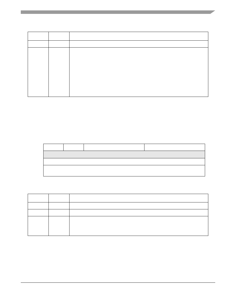
Interrupt Control Registers 1–63 (ICRn)
Each ICRn specifies the interrupt level (1–7) and the priority within the level (0–7). All ICRn registers can
be read, but only ICR8 to ICR63 can be written. It is software’s responsibility to program the ICRn
registers with unique and non-overlapping level and priority definitions. Failure to program the ICRn
registers in this matter can result in undefined behavior. If a specific interrupt request is completely unused,
the ICRn value can remain in its reset (and disabled) state.
6–4
LEVEL
Interrupt level. Represents the interrupt level currently being acknowledged.
3–0
PRI
Interrupt Priority. Represents the priority within the interrupt level of the interrupt currently
being acknowledged.
0 Priority 0
1 Priority 1
2 Priority 2
3 Priority 3
4 Priority 4
5 Priority 5
6 Priority 6
7 Priority 7
8 Mid-Point Priority associated with the fixed level interrupts only
7
6
5
4
3
2
1
0
R
0
0
IL
IP
W
Reset
0
0
0
0
0
0
0
0
Reg
Addr
See
for register offsets
Figure 13-9. Interrupt Control Registers 1–63 (ICRn)
Table 13-11. ICRn Field Descriptions
Bits
Name
Description
7–6
—
Reserved, should be cleared.
5–3
IL
Interrupt level. Indicates the interrupt level assigned to each interrupt input.
2–0
IP
Interrupt priority. Indicates the interrupt priority for internal modules within the
interrupt-level assignment. 000b represents the lowest priority and 111b represents the
highest. For the fixed level interrupt sources, the priority is fixed at the midpoint for the level,
and the IP field will always read as 000b.
Table 13-10. IACKLPR Field Descriptions (Continued)
Bits
Name
Description