Freescale Semiconductor MCF5480 User Manual
Page 266
MCF548x Reference Manual, Rev. 3
8-16
Freescale Semiconductor
8.4.5
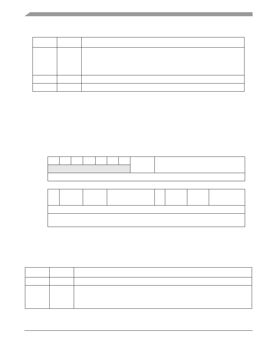
Address Attribute Trigger Registers (AATR, AATR1)
The AATR and AATR1,
, define address attributes and a mask to be matched in the trigger. The
register value is compared with address attribute signals from the processor’s local high-speed bus, as
defined by the setting of the trigger definition register (TDR) for AATR and the extended trigger definition
register (XTDR) for AATR1.
This register is expanded to include an optional ASID specification and a control bit that enables the use
of the ASID field.
describes AATR and AATR1 fields.
6–5
SZ
Size
00 Longword
01 Byte
10 Word
11 Reserved
4–3
TT
Transfer type. See the TT definition in
.
2–0
TM
Transfer modifier. See the TM definition in
.
31
30
29
28
27
26
25
24
23
22
21
20
19
18
17
16
R
0
0
0
0
0
0
0
ASIDCTRL
ATTRASID
W
Reset
0
0
0
0
0
0
0
0
0
0
0
0
0
0
0
0
15
14
13
12
11
10
9
8
7
6
5
4
3
2
1
0
R RM
SZM
TTM
TMM
R
SZ
TT
TM
W
Reset
0
0
0
0
0
0
0
0
0
0
0
0
0
1
0
1
Reg
Addr
CPU + 0x06 (AATR), 0x16( AATR1)
1
Write only. AATR and AATR1 are accessible in supervisor mode as debug control register 0x06 and 0x16
respectively using the WDEBUG instruction and through the BDM port using the
WDMREG
command.
Figure 8-9. Address Attribute Trigger Registers (AATR, AATR1)
Table 8-11. AATR and AATR1 Field Descriptions
Bits
Name Description
31–25
—
Reserved, should be cleared.
24
ASIDCTRL ABLR/ABHR/ATTR address breakpoint ASID enable. Corresponds to the ASID control enable for
the address breakpoint defined in ABLR, ABHR, and ATTR.
0 Disable ASID qualifier (reset default)
1 Enable ASID qualifier
Table 8-10. BAAR Field Descriptions
Bits
Name
Description