4 modem16 mode, Modem16 mode -38 – Freescale Semiconductor MCF5480 User Manual
Page 800
MCF548x Reference Manual, Rev. 3
26-38
Freescale Semiconductor
Figure 26-30. Waveform of Modem8 Mode
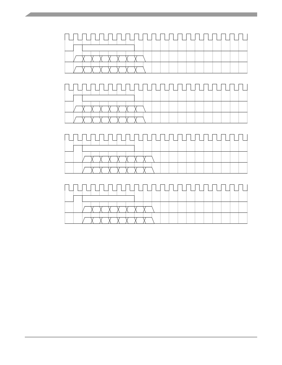
The transmitter starts to transmit the first bit at the rising edge of the PSCFSYNC or one clock after the
rising edge of the PSCFSYNC, according to the value in the DTS1 bit in the control register PSCSICR.
The SHDIR bit in the PSCSICR controls the order whether the LSB or the MSB is output first. The width
of the frame sync pulse makes no difference.
Similarly the receiver starts to receive a sample at the rising edge of the PSCFSYNC or one clock after the
rising edge.
The PSCFSYNC is sampled at the negative edge of the bit clock.
26.4.4
Modem16 Mode
shows an example of the waveform in 16-bit modem mode.
PSCBCLK
D7
D4 D3
D6 D5
D2 D1 D0
PSCFSYNC
PSCnTXD
D7
D4 D3
D6 D5
D2 D1 D0
PSCnRXD
DTS1 = 0 & SHDIR = 0
PSCBCLK
D0
D3 D4
D1 D2
D5 D6 D7
PSCFSYNC
PSCnTXD
D0
D3 D4
D1 D2
D5 D6 D7
PSCnRXD
DTS1 = 0 & SHDIR = 1
PSCBCLK
D7
D4 D3
D6 D5
D2 D1 D0
PSCFSYNC
PSCnTXD
D7
D4 D3
D6 D5
D2 D1 D0
PSCnRXD
DTS1 = 1 & SHDIR = 0
PSCBCLK
D0
D3 D4
D1 D2
D5 D6 D7
PSCFSYNC
PSCnTXD
D0
D3 D4
D1 D2
D5 D6 D7
PSCnRXD
DTS1 = 1 & SHDIR = 1