5 continuous selection format, Continuous selection format -29, Section 27.7.4.5, “continuous selection format – Freescale Semiconductor MCF5480 User Manual
Page 847
Functional Description
MCF548x Reference Manual, Rev. 3
Freescale Semiconductor
27-29
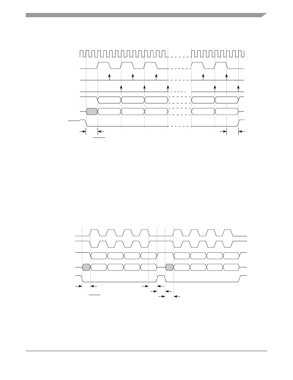
be visible on the master DSPISCK pin during the sampling of the last bit. The DSPISCK to CS delay must
be greater or equal to half of the DSPISCK period.
Figure 27-18. DSPI Modified Transfer Format
(MTFE = 1, CPHA = 1, Fsck = Fsys/4)
27.7.4.5
Continuous Selection Format
Some peripherals must be deselected between every transfer. Other peripherals must remain selected
between several sequential serial transfers. The continuous selection format provides the flexibility to
handle both cases. The continuous selection format is enabled by setting the DTFR[CONT].
When the CONT bit = 0, the DSPI drives the asserted chip select signals to their idle states in between
frames. The idle states of the chip select signals are selected by the DMCR[PCSIS] field.
shows the timing diagram for two 4-bit transfers with CPHA = 1 and CONT = 0.
Figure 27-19. Example of Non-Continuous Format (CPHA = 1, CONT = 0)
When the CONT bit = 1 and the DSPICSn signal for the next transfer is the same as for the current transfer,
the DSPICSn signal remains asserted for the duration of the two transfers. The delay between transfers
t
CSC
= PCSS to DSPISCK delay
t
ASC
= After DSPISCK delay
System Clock
1
2
3
4
5
6
PCSS
t
ASC
DSPISCK
Master Sample
Master DSPISOUT
Slave DSPISOUT
Slave Sample
t
CSC
DSPISCK
(CPOL = 0)
CS
n
t
ASC
DSPISCK
(CPOL = 1)
Master DSPISOUT
t
DT
t
CSC
t
CSC
= PCSS to DSPISCK delay
t
ASC
= After DSPISCK delay
t
DT
= Delay after transfer (minimum CS negation time)
Master DSPISIN
t
CSC