2 mode register 2 (pscmr2n), Mode register 2 (pscmr2n) -6, 2 mode register 2 (pscmr2 n ) – Freescale Semiconductor MCF5480 User Manual
Page 768
MCF548x Reference Manual, Rev. 3
26-6
Freescale Semiconductor
26.3.3.2
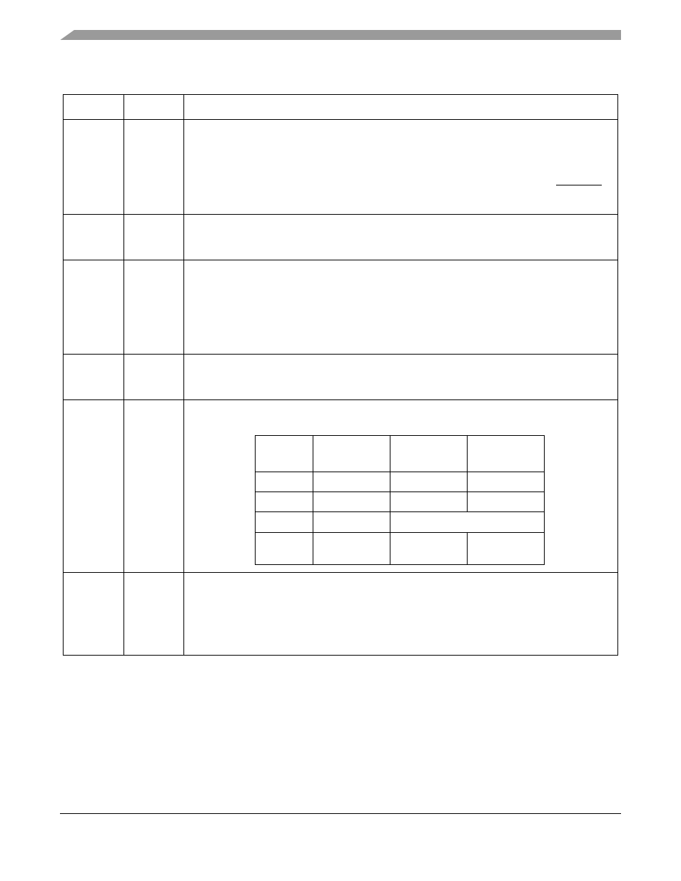
Mode Register 2 (PSCMR2n)
PSCMR2 controls some of the module configuration. It is accessed when the mode register pointer points
to PSCMR2, which occurs after any access to PSCMR1. Access to PSCMR2 does not change the pointer.
The pointer is set to the mode register 1 by reset or by a set pointer command using the MISC[2:0] bits in
the command register (PSCCR).
Table 26-3. PSCMR1n Field Descriptions
Bits
Name
Description
7
RXRTS
Receiver request-to-send (UART and SIR modes only). Allows the PSCnRTS output to control the
PSCnCTS input of the transmitting device to prevent receiver overrun. If both the receiver and
transmitter are incorrectly programmed for PSCnRTS control, PSCnRTS control is disabled for
both. Transmitter RTS control is configured in PSCMR2n[TxRTS].
0 The receiver has no effect on PSCnRTS.
1 When a valid start bit is received, PSCnRTS is negated if the UART's FIFO is full. PSCnRTS is
reasserted when the FIFO has an empty position available.
6
RXIRQ/
FU
Receiver interrupt select (all modes).
0 RxRDY is the source that generates IRQ or DMA request.
1 FU is the source that generates IRQ or DMA request.
5
ERR
Error mode (UART mode only). Configures the FIFO status bits, USRn[RB,FE,PE].
0 Character mode. The PSCSRn values reflect the status of the character at the top of the FIFO.
ERR must be 0 for correct A/D flag information when in multidrop mode.
1 Block mode. The PSCSRn values are the logical OR of the status for all characters reaching the
top of the FIFO since the last
RESET
ERROR
STATUS
command for the channel was issued. See
Section 26.3.3.5, “Command Register (PSCCRn)
.”
This bit is fixed to 1. It is provided for compatibility with previous implementations.
4–3
PM
Parity mode (UART mode only). Selects the parity or multidrop mode for the channel. The parity
bit is added to the transmitted character, and the receiver performs a parity check on incoming
data. The value of PM affects PT, as shown in the table displayed below in the PT field description.
2
PT
Parity type (UART mode only). PM and PT together select parity type (PM = 0x) or determine
whether a data or address character is transmitted (PM = 11).
1–0
BC
Bits per character (UART mode only). Select the number of data bits per character to be sent. The
values shown do not include start, parity, or stop bits.
00 5 bits
01 6 bits
10 7 bits
11 8 bits
PM
Parity Mode
Parity Type
(PT= 0)
Parity Type
(PT= 1)
00
With parity
Even parity
Odd parity
01
Force parity
Low parity
High parity
10
No parity
n/a
11
Multidrop mode Data character
Address
character