5 flexbus timing examples, 1 basic read bus cycle, Flexbus timing examples -15 – Freescale Semiconductor MCF5480 User Manual
Page 431: Basic read bus cycle -15
Functional Description
MCF548x Reference Manual, Rev. 3
Freescale Semiconductor
17-15
17.6.5
FlexBus Timing Examples
17.6.5.1
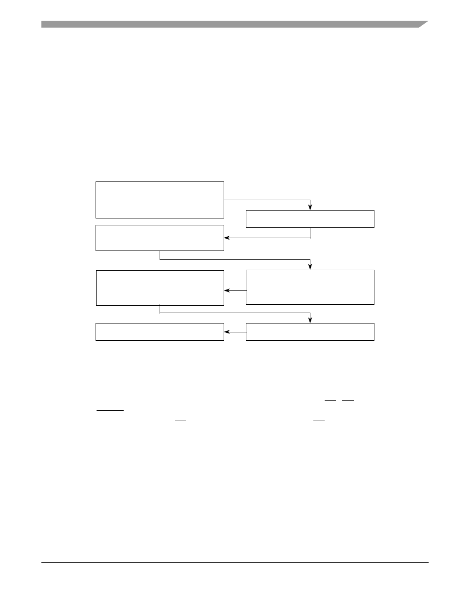
Basic Read Bus Cycle
During a read cycle, the MCF548x receives data from memory or from a peripheral device.
is
a read cycle flowchart.
NOTE
Throughout this chapter AD[X:0] is used to indicate an address bus that can
be 32-, 24-, or 16-bits in width. AD[31:Y] is a data bus that can be 32-, 16-,
or 8-bits wide.
Figure 17-8. Read Cycle Flowchart
The read cycle timing diagram is shown in
NOTE
In the following timing diagrams, the dotted lines indicate TA, OE, and
FBCSn timing when internal termination is used (CSCR[AA] = 1). The
external and internal TA assert at the same time; however, TA is not driven
externally for internally terminated bus cycles.
1. Select the appropriate slave device.
Drive data on AD[31:Y].
Assert TA (external termination).
2.
3.
1. Negate TA (external termination).
1. Decode address.
1. Set R/W to read.
Place address on AD[31:0].
Assert ALE.
2.
3.
1. Negate ALE.
Assert FBCSn.
2.
1. CS unit asserts internal TA (auto
acknowledge/internal termination).
Sample TA low and latch data.
2.
1. Start next cycle.
MCF548X
System