3 modem16 mode, 4 ac97 mode, Modem16 mode -51 – Freescale Semiconductor MCF5480 User Manual
Page 813: Ac97 mode -51
Software Environment
MCF548x Reference Manual, Rev. 3
Freescale Semiconductor
26-51
26.7.2.3
Modem16 Mode
The configuration sequence in modem16 mode is almost the same as in modem8 mode except that the first
write value to the SIM[2:0] in PSCSICR should be 3’b010.
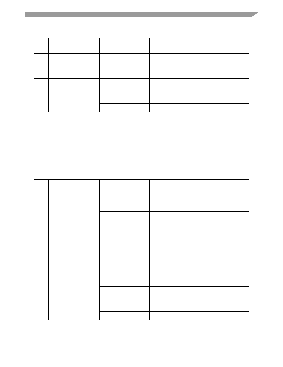
26.7.2.4
AC97 Mode
Applying a 12.288 MHz clock to the PSCBCLK input and programming the control registers are required
to initialize in AC97 mode. The following table describes a sample sequence.
5
PSCTFCR
0F
WRITE TAG=00
Not EOF
FRMEN=1
Enable frame mode
GR[2:0]=100
Granularity is 16 byte
6
PSCRFAR
00F0
ALARM[8:0]=0F0
Request is asserted if # of data >= 240
7
PSCTFAR
00F0
ALARM[8:0]=0F0
Request is asserted if # of empty >= 240
8
PSCCR
05
TC=01
Enable transmitter
RC=01
Enable receiver
Table 26-43. A Sample Initialization Sequence for AC97 Mode
Step
No.
Register
Value
Details
Meaning
1
PSCSICR
03
ACRB=1
Not cold reset
AWR=0
Not warm reset
SIM[2:0]=011
AC97 mode
2
PSCCR
20
MISC=010
Reset receiver and RxFIFO
30
MISC=011
Reset transmitter and TxFIFO
40
MISC=100
Reset all error status
3
PSCIMR
0300
IPC=0
Disable input port change interrupt
RxRDY or FU=1
Enable receiver interrupt/request
TxRDY=1
Enable transmitter interrupt/request
4
PSCRFCR
0F
WRITE TAG = 00
Not EOF
FRMEN=1
Enable frame mode
GR[2:0]=100
Granularity is 4 byte
5
PSCTFCR
0F
WRITE TAG = 00
Not EOF
FRMEN=1
Enable frame mode
GR[2:0]=100
Granularity is 16 byte
Table 26-42. Sample Initialization Sequence for Modem8 Mode (Continued)
Step
No.
Register
Value
Details
Meaning