5 aesu mode options and data packet descriptors, Aesu mode options and data packet descriptors -83 – Freescale Semiconductor MCF5480 User Manual
Page 685
EU Specific Data Packet Descriptors
MCF548x Reference Manual, Rev. 3
Freescale Semiconductor
22-83
22.14.5 AESU Mode Options and Data Packet Descriptors
The AESU mode register contains three bits which are used to program the AESU. The mode register is
cleared when the AESU is reset or re-initialized. Setting a reserved mode bit will generate a data error. If
the mode register is modified during processing, a context error will be generated.
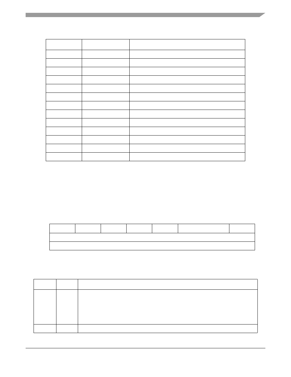
shows the AESU options that are programmable via the PMODE field in the descriptor
header.
describes AESU mode register fields.
LEN_2
IV Length
NULL
PTR_2
IV Pointer
NULL
LEN_3
Key Length
NULL
PTR_3
Key Pointer
NULL
LEN_4
Data In Length
NULL
PTR_4
Data In Pointer
NULL
LEN_5
Data Out Length
Number of random bytes to be written (multiple of 4)
PTR_5
Data Out Pointer
Address where random numbers are written
LEN_6
IV Out Length
NULL
PTR_6
IV Out Pointer
NULL
LEN_7
MAC Out Length
NULL
PTR_7
MAC Out Pointer
NULL
PTR_NEXT
Next Descriptor Pointer Pointer to next data packet descriptor
7
6
5
4
3
2
1
0
Field
ECM
—
FM
IM
—
CM
ED
Reset
0000_0000
Loc
PMODE Field in DPD Header
Figure 22-49. AESU Mode Options
Table 22-76. AESU Mode Register Field Descriptions
Bits
Name
Description
7
ECM
Extend Cipher Mode. Used in combination with the cipher mode (CM field) to define the mode
of AES operation.
0 No Cipher Mode extension in use, Cipher Mode selected by CM values
1 Extended Cipher Mode. Indicates AES-Counter Mode with CBC-MAC (AES-CCM) is in use.
Note: CM must be set to 00 when Extend Cipher Mode is set, otherwise an error will be
generated.
6
—
Reserved, should be cleared.
Table 22-75. RNG Descriptor Format (Continued)
Field Name
Value/Type
Description