Freescale Semiconductor MCF5480 User Manual
Page 826
MCF548x Reference Manual, Rev. 3
27-8
Freescale Semiconductor
an SPI master, the DTFR[CTAS] field in the command portion of the Tx FIFO entry selects which of the
DCTAR registers is used.
In slave mode, a subset of the bitfields in only the DCTAR0 registers are used to set the slave transfer
attributes. See the individual bit descriptions of this register for details on which bits are used in slave
modes.
31
30
29
28
27
26
25
24
23
22
21
20
19
18
17
16
R
0
TRSZ
CPOL CPHA LSBFE
PCSSCK
PASC
PDT
PBR
W
Reset
0
1
1
1
1
0
0
0
0
0
0
0
0
0
0
0
15
14
13
12
11
10
9
8
7
6
5
4
3
2
1
0
R
CSSCK
ASC
DT
BR
W
Reset
0
0
0
0
0
0
0
0
0
0
0
0
0
0
0
0
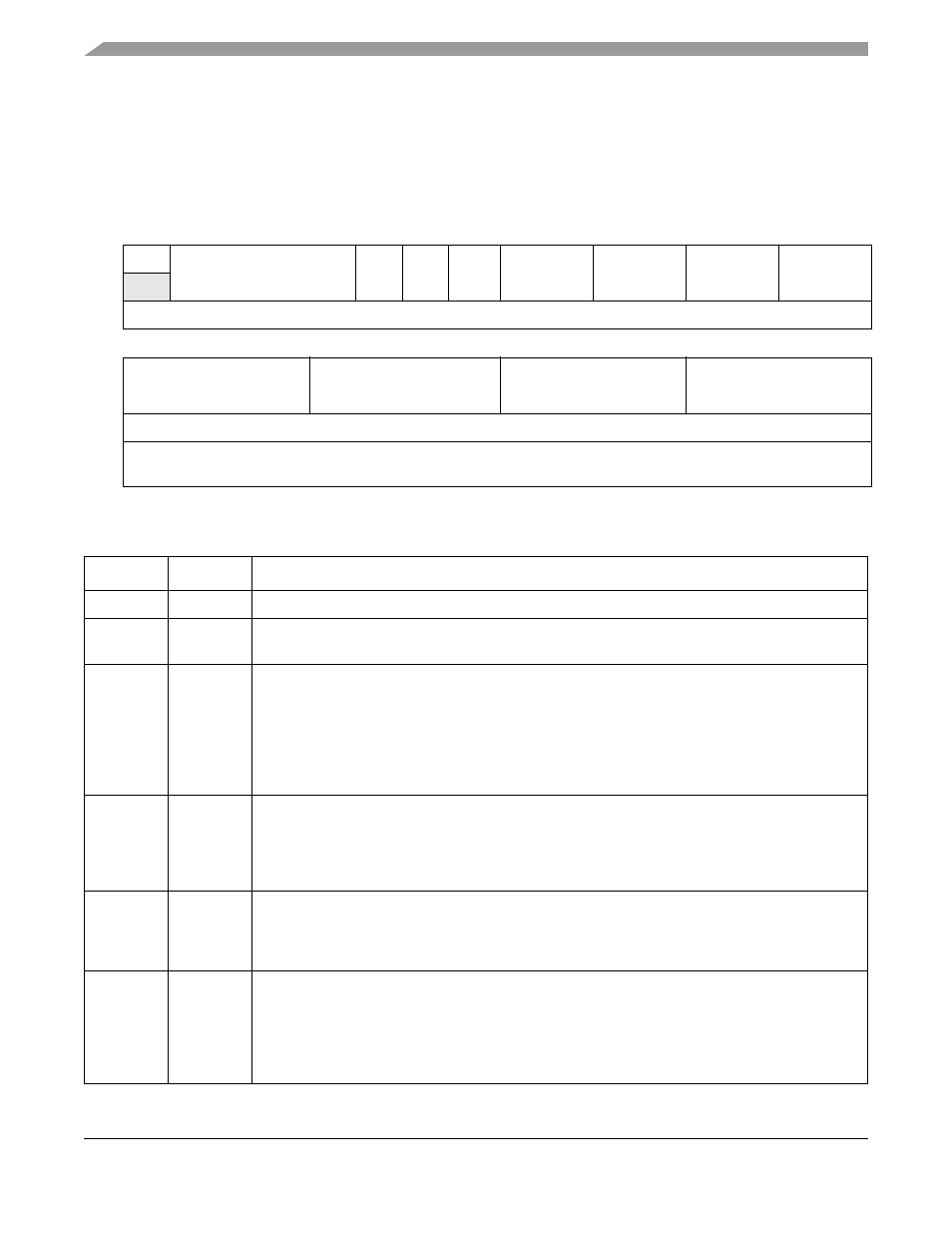
Reg
Addr
MBAR + 0x8A0C (DCTAR0), 0x8A10 (DCTAR1), 0x8A14 (DCTAR2), 0x8A18 (DCTAR3),
0x8A1C (DCTAR4), 0x8A20 (DCTAR5), 0x8A24 (DCTAR6), 0x8A28 (DCTAR7)
Figure 27-4. DSPI Clock and Transfer Attributes Register (DCTARn)
Table 27-5. DCTAR Field Descriptions
Bits
Name
Description
31
—
Reserved, should be cleared.
30–27
TRSZ
Transfer size. Selects the number of bits transferred per frame. The TRSZ field is used in master
mode and slave mode.
lists the transfer sizes.
26
CPOL
Clock polarity. Selects the inactive state of the clock (DSPISCK). This bit is used in both master and
slave mode. For successful communication between serial devices, the devices must have identical
clock polarities. As explained in
Section 27.7.4.5, “Continuous Selection Format
,” switching between
clock polarities without stopping the DSPI can cause errors in the transfer due to the peripheral
device interpreting the switch of clock polarity as a valid clock edge.
0 The inactive state of DSPISCK is low
1 The inactive state of DSPISCK is high
25
CPHA
Clock phase. The CPHA bit selects which edge of DSPISCK causes data to change and which edge
causes data to be captured. This bit is used in both master and slave mode. For successful
communication between serial devices, the devices must have identical clock phase settings.
0 Data is captured on the leading edge of DSPISCK and changed on the following edge
1 Data is changed on the leading edge of DSPISCK and captured on the following edge
24
LSBFE
LSB first enable. Selects if the LSB or MSB of the frame is transferred first. This bit is only used in
master mode.
0 Data is transferred MSB first
1 Data is transferred LSB first
23–22
PCSSCK
CS to SCK delay prescaler. The PCSSCK field selects the prescaler value for the delay between
assertion of
DSPICS and the first edge of the DSPISCK. This field is only used in master mode.
00 1 clock DSPICS to DSPISCK delay prescaler
01 3 clock DSPICS to DSPISCK delay prescaler
10 5 clock DSPICS to DSPISCK delay prescaler
11 7 clock DSPICS to DSPISCK delay prescaler