5 ac97 mode, Ac97 mode -39 – Freescale Semiconductor MCF5480 User Manual
Page 801
Functional Description
MCF548x Reference Manual, Rev. 3
Freescale Semiconductor
26-39
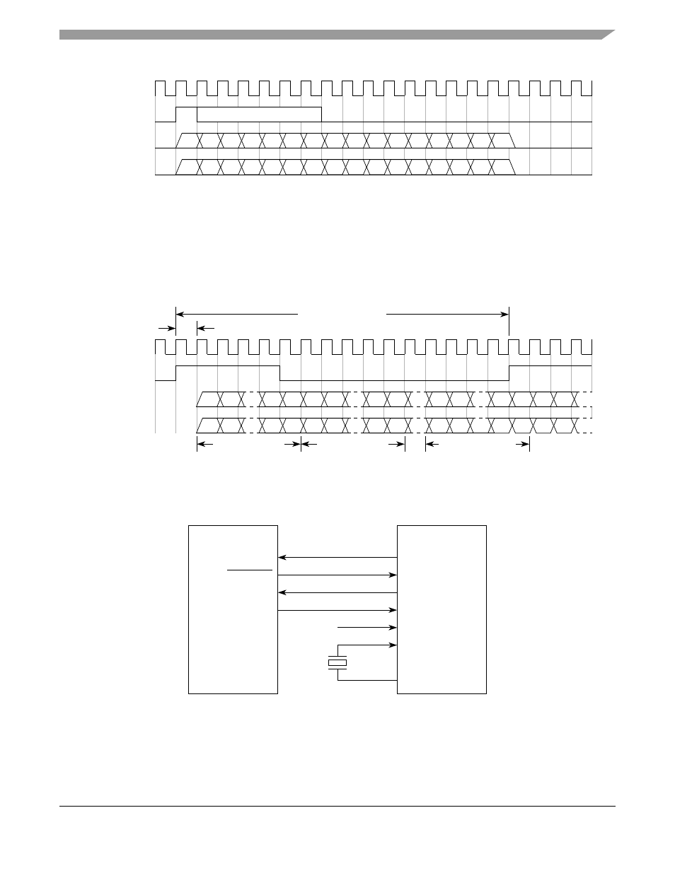
Figure 26-31. Waveform of Modem16 Mode
The function of this mode is the same as 8-bit modem mode except that the transmit/receive data length is
16 bit.
26.4.5
AC97 Mode
shows the waveform in AC97 modem mode.
Figure 26-32. Waveform of AC97 Mode
In AC97 mode, the PSCBCLK is the bit clock input and, different from 8/16 bit modem mode, the
PSCnRTS is the frame sync output.
shows an example connection to a AC97 CODEC chip.
Figure 26-33. An Example Connection to AC97 CODEC
PSCBCLK
D15
D12 D11
D14 D13
D10 D9
PSCFSYNC
PSCnTXD
PSCnRXD
D4 D3
D6 D5
D2 D1 D0
D8 D7
D15
D12 D11
D14 D13
D10 D9
D4 D3
D6 D5
D2 D1 D0
D8 D7
PSCBCLK
D15
D1 D0
D14
D19 D18
PSCnRTS
PSCnTXD
PSCnRXD
D19 D18
D0
D1
D1
D15
D1 D0
D14
D19 D18
D19 D18
D0
D1
D1
81.4 ns (12.288 MHz)
20.8 µs (48.0 kHz)
D0
D0
D15
D15
D14
D14
Slot #0 (16-bit)
Slot #1 (20-bit)
Slot #12 (20-bit)
BITCLK
SYNC
XTL_IN
XTL_OUT
SDATA_IN
RESET
SDATA_OUT
AC97 CODEC
PSC_BIT_CLK
PSC_RTS
PSC_RXD
PSC_TXD
PSC