Chapter 19 pci bus controller, 1 introduction, 1 block diagram – Freescale Semiconductor MCF5480 User Manual
Page 485: 2 overview, 3 features, Chapter 19, Pci bus controller, Introduction -1, Block diagram -1, Overview -1
MCF548x Reference Manual, Rev. 3
Freescale Semiconductor
19-1
Chapter 19
PCI Bus Controller
19.1
Introduction
This chapter details the operation of the PCI bus controller for the MCF548x device. The PCI Bus Arbiter
Chapter 20, “PCI Bus Arbiter Module.”
19.1.1
Block Diagram
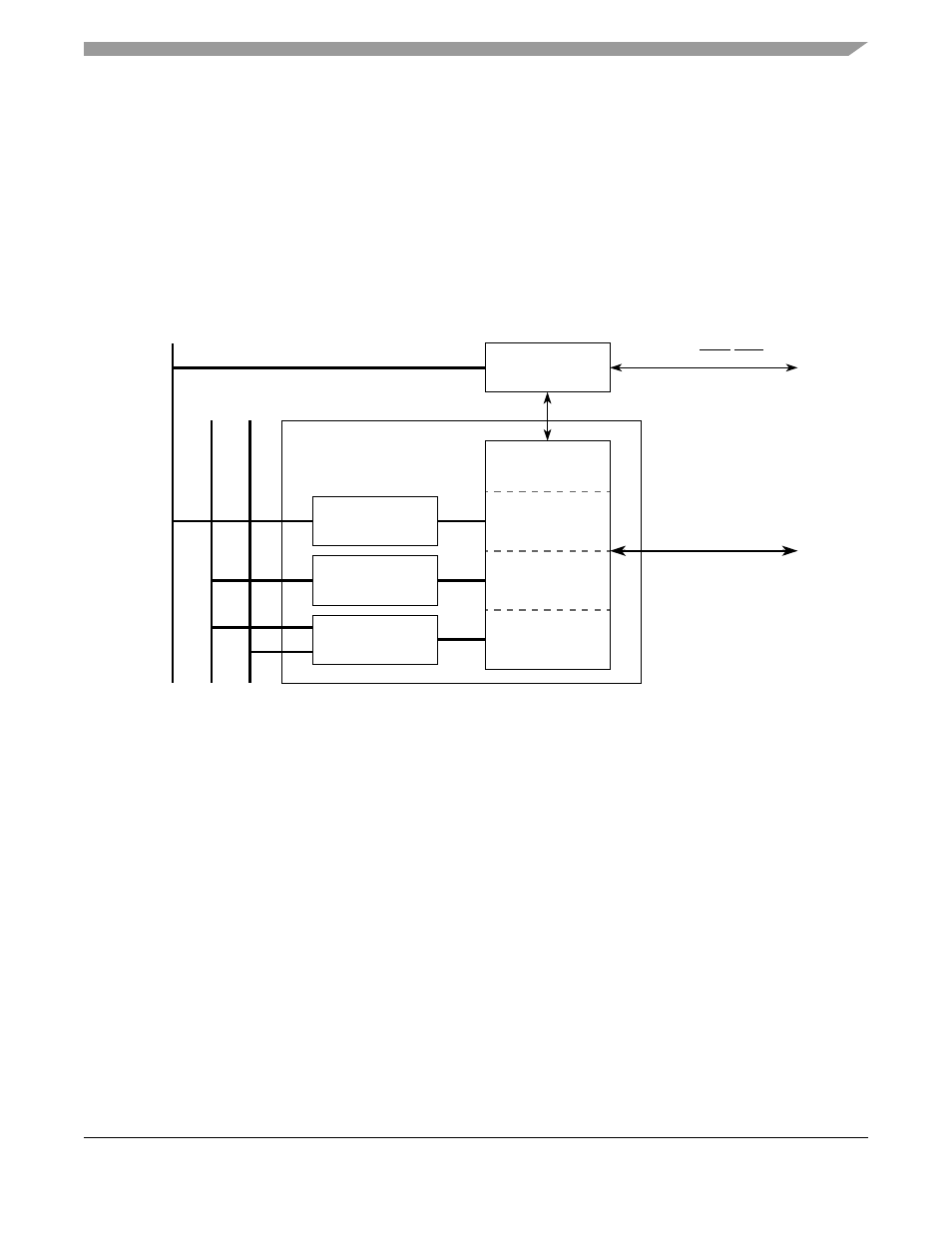
Figure 19-1. PCI Block Diagram
19.1.2
Overview
The peripheral component interface (PCI) bus is a high-performance bus with multiplexed address and
data lines. It is especially suitable for high data-rate applications.
The PCI controller module supports a 32-bit PCI initiator (master) and target interface. As a target, access
to the internal XL bus is supported. As an initiator, the PCI controller is coupled directly to the XL bus (as
a slave) and available on the communication subsystem as a multichannel DMA peripheral.
The MCF548x contains PCI central resource functions such as the PCI Arbiter (
) and PCI reset control. The PCI bus clock must be provided by an external source. It must
be phase aligned and either equal to 1, 1/2, or 1/4 the frequency of the system clock.
19.1.3
Features
The following PCI features are supported in the MCF548x:
•
Supports system clock: PCI clock frequency ratios 1:1, 2:1, and 4:1
•
Uses external CLKIN as clock reference
PCI
Controller
Configuration
Interface
Target
Interface
Initiator
Interface
External PCI Bus
Req/Gnt
External REQ/GNT
Master Bus
Target
Configuration
PCI
Arbiter
Co
mm Bu
s
XL
B
u
s
Sla
ve Bus (IP Bus)
Master Bus/
Comm Bus Initiator
PCI Controller Block