2 overview, Overview -2, Figure 25-2 – Freescale Semiconductor MCF5480 User Manual
Page 754: Figure 25-3
MCF548x Reference Manual, Rev. 3
25-2
Freescale Semiconductor
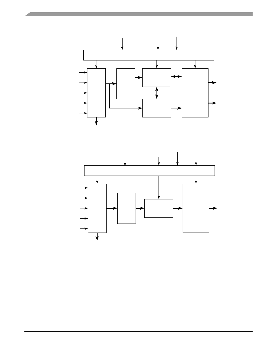
Figure 25-2. Fixed Timer Channel Conceptual Block Diagram
Figure 25-3. Variable Timer Channel Conceptual Block Diagram
25.1.2
Overview
The CTM module provides two functions for the communications complex. First, it can be configured to
run as a baud clock generator for the communications channels. Second, it can be used as a task initiator
for the DMA. There are three main functional blocks within the CTM that accomplish these functions: the
slave bus interface, the fixed timer channel, and the variable timer channel.
The slave bus interface to the CTM processes tasks such as the address decode, clock synchronization,
clock pre-scaling, and read/write enable decode.
mode
15-bit Percent
(High Time)
cAcknowledge
clk
Miscellaneous Block
Counter
timerInterrupt
cInitiator
Comparators
source[3:0]
percent[1:0]
counterReference[15:0]
TCRselect
dataRd[23:0]
Register
Percent
16-bit Period
Counter
Internal Bus
mode
externalClkIn
cAcknowledge
clk
Miscellaneous Block
cInitiator
Comparator
source
percent[1:0]
counterReference[23:0]
TCRselect
dataRd[23:0]
Register
Percent
24-bit Percent
Counter
Internal Bus