2 multidrop mode, Multidrop mode -36 – Freescale Semiconductor MCF5480 User Manual
Page 798
MCF548x Reference Manual, Rev. 3
26-36
Freescale Semiconductor
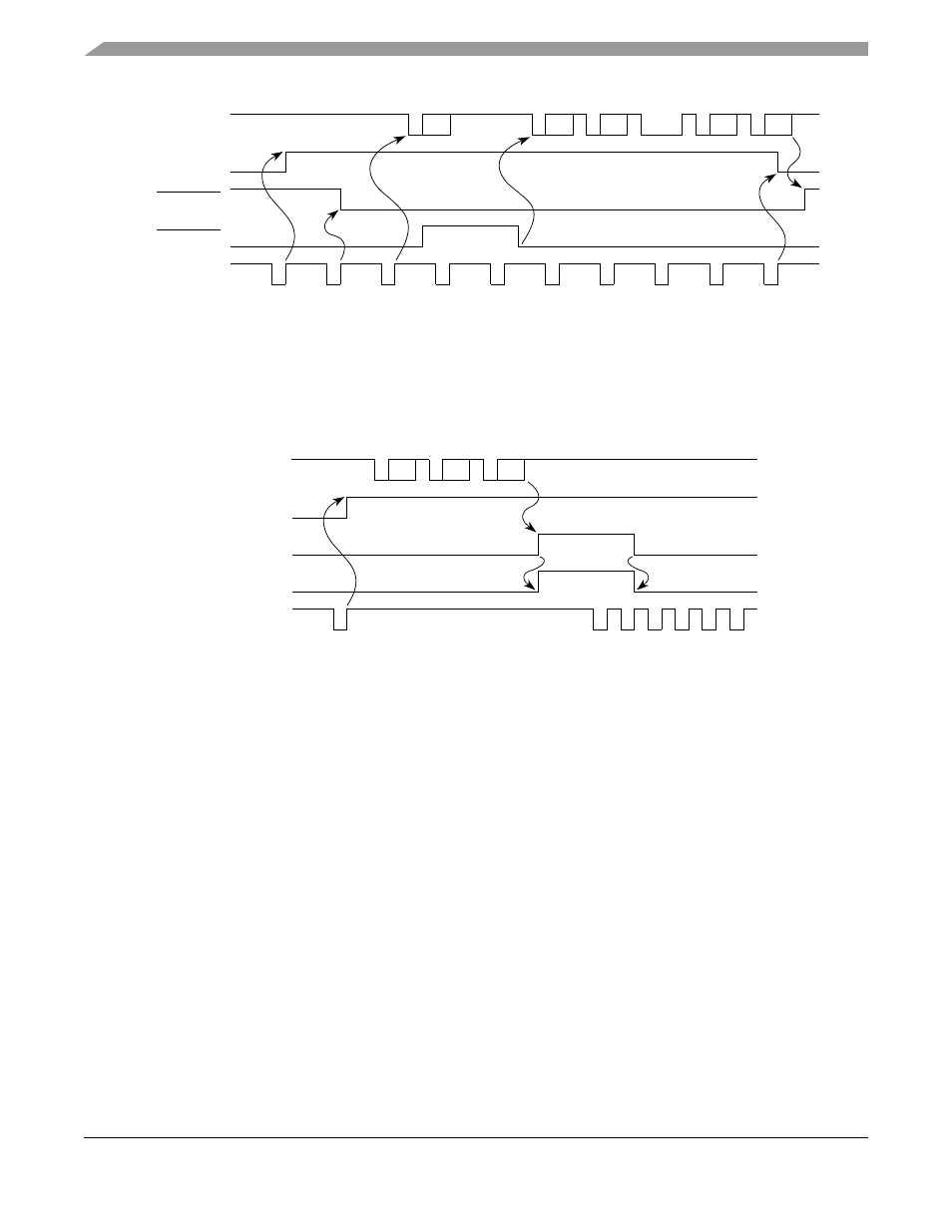
Figure 26-28. Modem Control and Transmitter
If PSCnRTS is programmed to be RxRTS, the PSCnRTS output is automatically asserted and negated by
the receiver. The PSCnRTS is asserted when the receiver is ready and the number in the RxFIFO is less
than the threshold, and PSCnRTS is negated when the receiver is disabled or the RxFIFO has more data
than the threshold.
Figure 26-29. Modem Control and Receiver
26.4.2
Multidrop Mode
The UART can be programmed to operate in a wakeup mode for multidrop or multiprocessor applications.
The mode is selected by setting bits 3 and 4 in mode register 1 (PSCMR1). This mode of operation allows
the master station to be connected to several slave stations (a maximum of 256). In this mode, the master
transmits an address character followed by a block of data characters targeted for one of the slave stations.
The slave stations have their channel receivers disabled. However, they continuously monitor the data
stream sent out by the master station. When an address character is sent by the master, the slave receiver
channel notifies its respective CPU by setting the RxRDY bit in the USR and generating an interrupt (if
programmed to do so). Each slave station CPU then compares the received address to its station address
and enables its receiver if it wishes to receive the subsequent data characters or block of data from the
master station. Slave stations not addressed continue to monitor the data stream for the next address
character. Data fields in the data stream are separated by an address character. After a slave receives a
block of data, the slave station's CPU disables the receiver and initiates the process again.
A transmitted character from the master station consists of a start bit, a programmed number of data bits,
an address/data (A/D) bit flag, and a programmed number of stop bits. The A/D bit identifies the type of
character being transmitted to the slave station. The character is interpreted as an address character if the
Module_En_B
Enable
TX
Assert
RTS
Write
C1
Write
C2
Write
C3
Start
Break
Write
C4
End
Break
Write
C5
Disable
TX
C1
C2
C3
C4
C5
Break
PSCnTXD
Transmitter
PSCnRTS
Enabled
PSCnCTS
Command
from Bus
Module_En_B
Read
Status
Read
Status
Read
Status
C1
C2
PSC_RXD
Receiver
FU
Enabled
PSC_RTS
Command
from Bus
C3
Read
Data
Read
Data
Read
Data
Enable
Receiver