Figure 8-13, Define regions in, Table 8-15 describes ablr and ablr1 fields – Freescale Semiconductor MCF5480 User Manual
Page 272: Table 8-16 describes abhr and abhr1 fields, Commands
MCF548x Reference Manual, Rev. 3
8-22
Freescale Semiconductor
describes ABLR and ABLR1 fields.
describes ABHR and ABHR1 fields.
8.4.9
Data Breakpoint and Mask Registers (DBR/DBR1, DBMR/DBMR1)
The data breakpoint registers (DBR/DBR1,
), specify data patterns used as part of the trigger
into debug mode. DBRn bits are masked by setting corresponding DBMR bits, as defined in TDR.
DBR and DBR1 are accessible in supervisor mode as debug control register 0x0E and 0x1E, using the
WDEBUG instruction and through the BDM port using the
RDMREG
and
WDMREG
commands.
31
30
29
28
27
26
25
24
23
22
21
20
19
18
17
16
R
AD
Reset
0
0
0
0
0
0
0
0
0
0
0
0
0
0
0
0
15
14
13
12
11
10
9
8
7
6
5
4
3
2
1
0
R
AD
Reset
0
0
0
0
0
0
0
0
0
0
0
0
0
1
0
1
Reg
Addr
CPU + 0x0D (ABLR); 0x1D (ABLR1); 0x0C (ABHR); 0x1C (ABHR1)
1
ABHR and ABHR1 are accessible in supervisor mode as debug control registers 0x0C and 0x1C, using the
WDEBUG instruction and via the BDM port using the
RDMREG
and
WDMREG
commands.
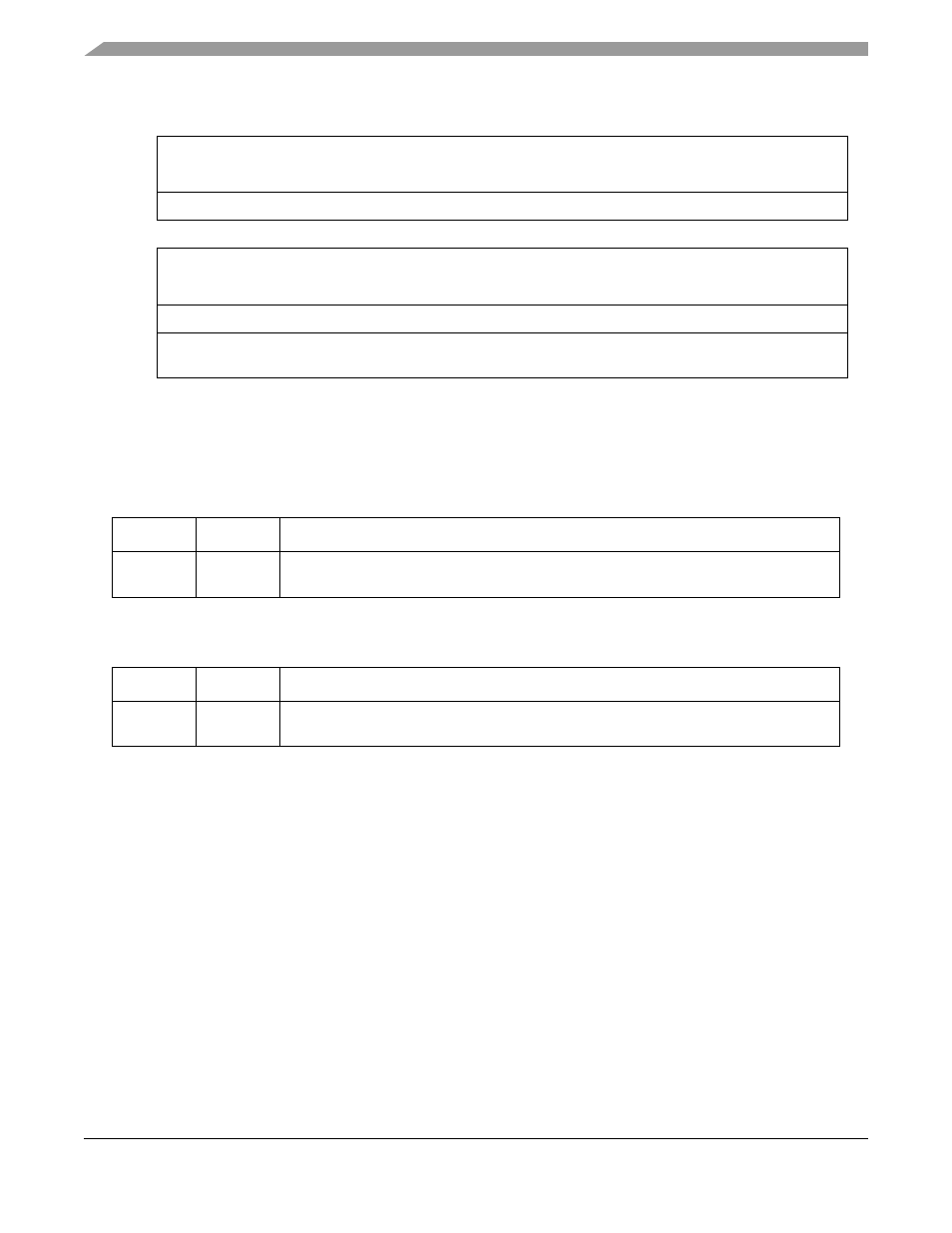
Figure 8-13. Address Breakpoint Registers (ABLR, ABHR, ABLR1, ABHR1)
Table 8-15. ABLR and ABLR1 Field Description
Bits
Name
Description
31–0
AD
Low address. Holds the 32-bit address marking the lower bound of the address breakpoint
range. Breakpoints for specific addresses are programmed into ABLR or ABLR1.
Table 8-16. ABHR and ABHR1 Field Description
Bits
Name
Description
31–0
AD
High address. Holds the 32-bit address marking the upper bound of the address breakpoint
range.