1 processor status/debug data (pstddata[7:0]), Processor status/debug data (pstddata[7:0]) -3, Table 8-1 – Freescale Semiconductor MCF5480 User Manual
Page 253: Describes debug module signals. al
Signal Descriptions
MCF548x Reference Manual, Rev. 3
Freescale Semiconductor
8-3
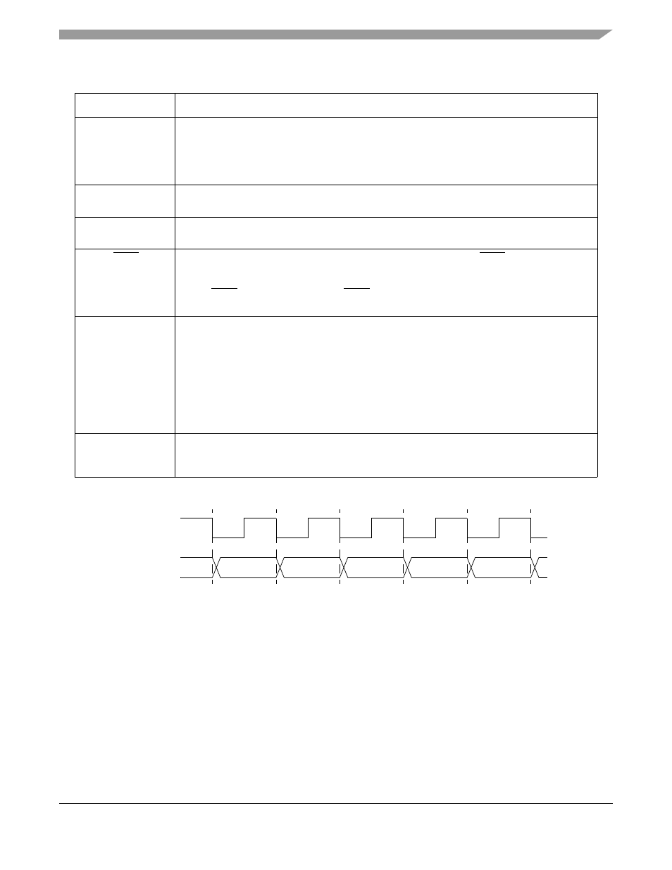
shows PSTCLK timing with respect to PSTDDATA.
Figure 8-2. PSTCLK Timing
8.2.1
Processor Status/Debug Data (PSTDDATA[7:0])
Processor status data outputs are used to indicate both processor status and captured address and data
values. They operate at half the processor’s frequency. Given that real-time trace information appears as a
sequence of 4-bit data values, there are no alignment restrictions; that is, the processor status (PST) values
and operands may appear on either nibble of PSTDDATA[7:0]. The upper nibble (PSTDDATA[7:4]) is the
more significant and yields values first.
CSR controls capturing of data values to be presented on PSTDDATA. Executing the WDDATA
instruction captures data that is displayed on PSTDDATA too. These signals are updated each processor
cycle and display two values at a time for two processor clock cycles.
Table 8-1. Debug Module Signals
Signal
Description
DSCLK
Development Serial Clock-Internally synchronized input. (The logic level on DSCLK is validated
if it has the same value on two consecutive rising bus clock edges.) Clocks the serial
communication port to the debug module during packet transfers. Maximum frequency is
PSTCLK/5. At the synchronized rising edge of DSCLK, the data input on DSI is sampled and
DSO changes state.
DSI
Development Serial Input -Internally synchronized input that provides data input for the serial
communication port to the debug module, once the DSCLK has been seen as high (logic 1).
DSO
Development Serial Output -Provides serial output communication for debug module responses.
DSO is registered internally. The output is delayed from the validation of DSCLK high.
BKPT
Breakpoint - Input used to request a manual breakpoint. Assertion of BKPT puts the processor
into a halted state after the current instruction completes. Halt status is reflected on processor
status/debug data signals (PSTDDATA[7:0]) as the value 0xF. If CSR[BKD] is set (disabling
normal BKPT functionality), asserting BKPT generates a debug interrupt exception in the
processor.
PSTCLK
Processor Status Clock - Half-speed version of the processor clock. Its rising edge appears in the
center of the two-processor-cycle window of valid PSTDDATA output. See
. PSTCLK
indicates when the development system should sample PSTDDATA values.
If real-time trace is not used, setting CSR[PCD] keeps PSTCLK and PSTDDATA outputs from
toggling without disabling triggers. Non-quiescent operation can be reenabled by clearing
CSR[PCD], although the external development systems must resynchronize with the PSTDDATA
output.
PSTCLK starts clocking only when the first non-zero PST value (0xC, 0xD, or 0xF) occurs during
system reset exception processing.
describes PST values.
PSTDDATA[7:0]
Processor Status/Debug Data - These outputs, which change on the negative edge of PSTCLK,
indicate both processor status and captured address and data values and are discussed more
thoroughly in
Section 8.2.1, “Processor Status/Debug Data (PSTDDATA[7:0])
.”
PSTCLK
STDDATA