2 external signals, 1 cantx[1:0, 2 canrx[1:0 – Freescale Semiconductor MCF5480 User Manual
Page 575: 3 memory map/register definition, 1 flexcan memory map, External signals -5, Cantx[1:0] -5, Canrx[1:0] -5, Memory map/register definition -5, Flexcan memory map -5
External Signals
MCF548x Reference Manual, Rev. 3
Freescale Semiconductor
21-5
21.2
External Signals
The FlexCAN module has two I/O signals connected to the external MPU pins: CANTX and CANRX.
Note that the general purpose I/O (GPIO) must be configured to enable the peripheral function of the
) prior to configuring a FlexCAN channel.
21.2.1
CANTX[1:0]
CANTXn transmits serial data to the CAN bus transceiver.
21.2.2
CANRX[1:0]
CANRXn receives serial data from the CAN bus transceiver.
21.3
Memory Map/Register Definition
21.3.1
FlexCAN Memory Map
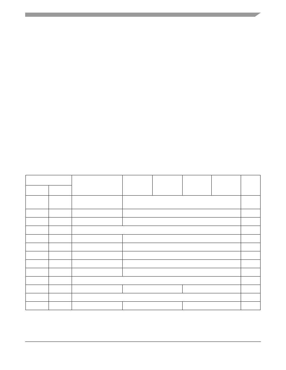
The FlexCAN module address space is split into 128 bytes starting at the base address, and then an extra
256 bytes starting at the base address +128. The upper 256 are fully used for the message buffer structures,
Section 21.4.2, “Message Buffer Memory Map
.” Out of the lower 128 bytes, only part is
occupied by various registers.
Table 21-1. FlexCAN Memory Map
MBAR Offset
Name
Byte0
Byte1
Byte2
Byte3
Access
FlexCAN0 FlexCAN1
0xA000
0xA800
FlexCAN module
configuration register
CANMCR
S
0xA004
0xA804
FlexCAN control register
CANCTRL
S/U
0xA008
0xA808
Timer register
TIMER
S/U
0xA00C
0xA80C
Reserved
—
0xA010
0xA8010
Rx global mask
RXGMASK
S/U
0xA014
0xA814
Rx buffer 14 mask
RX14MASK
S/U
0xA018
0xA818
Rx buffer 15 mask
RX15MASK
S/U
0xA01C
0xA81C
Error counter register
ERRCNT
S/U
0xA020
0xA820
Error and status register
ERRSTAT
S/U
0xA024
0xA824
Reserved
—
0xA028
0xA828
Interrupt mask register
Reserved
IMASK
S/U
0xA02C
0xA82C
Reserved
—
0xA030
0xA830
Interrupt flag register
Reserved
IFLAG
S/U