14 axis bus – Lenze 8400 TopLine User Manual
Page 853
Lenze · 8400 TopLine · Reference manual · DMS 6.0 EN · 06/2014 · TD05/TD14
853
14
Axis bus
14.3
IO axis bus
_ _ _ _ _ _ _ _ _ _ _ _ _ _ _ _ _ _ _ _ _ _ _ _ _ _ _ _ _ _ _ _ _ _ _ _ _ _ _ _ _ _ _ _ _ _ _ _ _ _ _ _ _ _ _ _ _ _ _ _ _ _ _ _
Error status
By setting the
.bSetFail_DigOut input to TRUE, each node can set the IO axis bus into
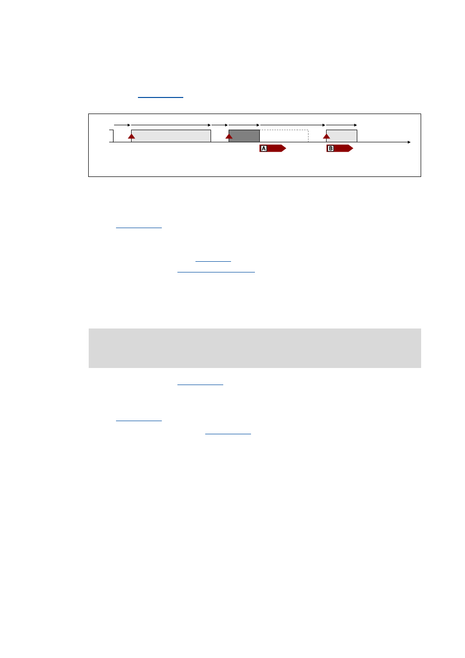
the "Error" status. The node signalises this by reducing the HIGH pulse length to 620 μs:
[14-6] Synchronisation cycle (error status)
All other nodes detect the "error status" due to the changed pulse length which has the following
effect:
.bFail_DigIn output is set to TRUE. This digital signal can be used for any
application within the function block interconnection.
•
From version 12.00.00:
• The error response set in
is activated (Lenze setting: "Fault").
• The error message "
" is entered into the logbook.
• The nodes are now error-passive, i.e. they cannot signalise any further errors in order that the
HIGH edge for synchronisation can be detected after 2 ms.
Reset "error" status
A FALSE/TRUE edge at the
.bResetFail input (for the master) serves to reset the "error"
status again. The master signalises this by providing a LOW pulse for 3 ms.
All other nodes detect the error reset due to this signal, which has the following effect:
.bFail_DigIn output is reset to FALSE.
• After a delay time of 2 ms, the
.bResetFailIn output is set for 3 ms to TRUE. This
digital signal can be used within the function block interconnection to e.g. reset errors.
A node signalises "Error" by a reduced HIGH pulse length
"Error" status is active for all nodes
W
9
9
V
V
V
V
V
V
Note!
The "error" status can only be reset by the master!