3 basic settings, Basic settings, 5motor control (mctrl) – Lenze 8400 TopLine User Manual
Page 215
Lenze · 8400 TopLine · Reference manual · DMS 6.0 EN · 06/2014 · TD05/TD14
215
5
Motor control (MCTRL)
5.8
Sensorless control for synchronous motors (SLPSM)
_ _ _ _ _ _ _ _ _ _ _ _ _ _ _ _ _ _ _ _ _ _ _ _ _ _ _ _ _ _ _ _ _ _ _ _ _ _ _ _ _ _ _ _ _ _ _ _ _ _ _ _ _ _ _ _ _ _ _ _ _ _ _ _
5.8.3
Basic settings
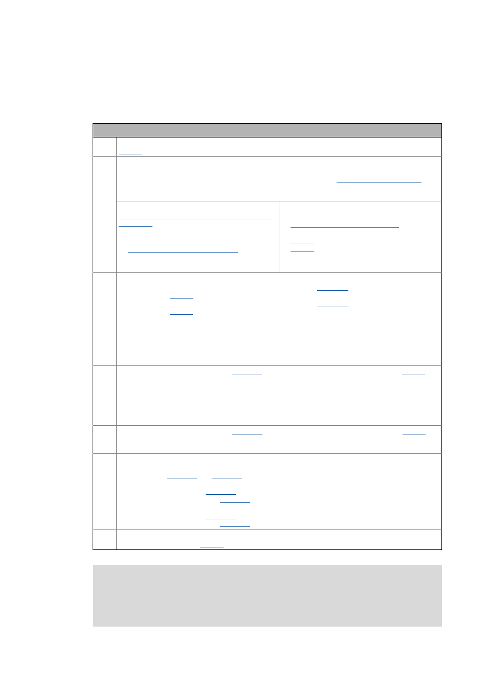
The following "Initial commissioning steps" must be performed to commission the sensorless
control for synchronous motors:
Initial commissioning steps
1. Select motor control:
= "3: SLPSM: Sensorless PSM"
2. Set the motor selection/motor data
• When selecting and parameterising the motor, the motor nameplate data and the equivalent circuit
diagram data are relevant. Detailed information can be found in the "
chapter.
Depending on the motor manufacturer, proceed as follows:
Lenze motor:
Selecting a motor from the motor catalogue in the
- or -
1.Set the motor nameplate data
2.
Automatic motor data identification
Third party manufacturer's motor:
1.Set the motor nameplate data
2.
Automatic motor data identification
or set known
equivalent circuit diagram manually:
: Motor stator resistance
: Motor stator leakage inductance
3. Set speed switching thresholds between open-loop and closed-loop controlled operation:
• Set transition speed from closed-loop to open-loop operation in
in [%] with regard to the rated
motor speed (
).
• Set transition speed from closed-loop to open-loop operation in
in [%] with regard to the rated
motor speed (
).
Tip!
• With voltage-adjusted motors, a speed switching threshold of 10 % is recommended.
• As a rule of thumb, the speed switching threshold should be selected as follows:
4. Set open-loop accelerating current in
in [%] with regard to the rated motor current (
• This value defines the height of the current that is injected during the acceleration process.
• The accelerating current must be dimensioned so that the required torque in the lower speed range can
always be reached (acceleration torque + load torque):
5. Set open-loop steady-state current in
in [%] with regard to the rated motor current (
).
• This value defines the height of the current for processes without acceleration (e.g. standstill or constant
setpoint speed ).
6. For improving the operating characteristics:
If required, adapt the filter time for reconstructing the rotor position and the actual speed value through the
motor model in
and
• We recommend using the Lenze setting:
Filter time rotor position (
) = 3 ms
Filter time actual speed value (
) = 5 ms
• Deviant from this, the following value range can be used:
Filter time rotor position (
) = 2 ... 5 ms
Filter time actual speed value (
) = 3 ... 8 ms
7. For protecting the motor from demagnetisation:
Note!
The Lenze settings of the current controller are predefined for a power-adapted motor.
For an optimal drive behaviour of a synchronous motor, we recommend to adapt the
controller settings.
C00996/1...2 [%]
U
Rated, motor
[V]
U
Rated, FI
[V]
---------------------------------------
10
⋅
=
C00995/1 [%]
M
Meax
[Nm]
M
Rated
[Nm]
-------------------------------
I
Rated, motor
[A] 1.3
⋅
⋅
=