5motor control (mctrl) – Lenze 8400 TopLine User Manual
Page 142
5
Motor control (MCTRL)
5.1
Motor selection/Motor data
142
Lenze · 8400 TopLine · Reference manual · DMS 6.0 EN · 06/2014 · TD05/TD14
_ _ _ _ _ _ _ _ _ _ _ _ _ _ _ _ _ _ _ _ _ _ _ _ _ _ _ _ _ _ _ _ _ _ _ _ _ _ _ _ _ _ _ _ _ _ _ _ _ _ _ _ _ _ _ _ _ _ _ _ _ _ _ _
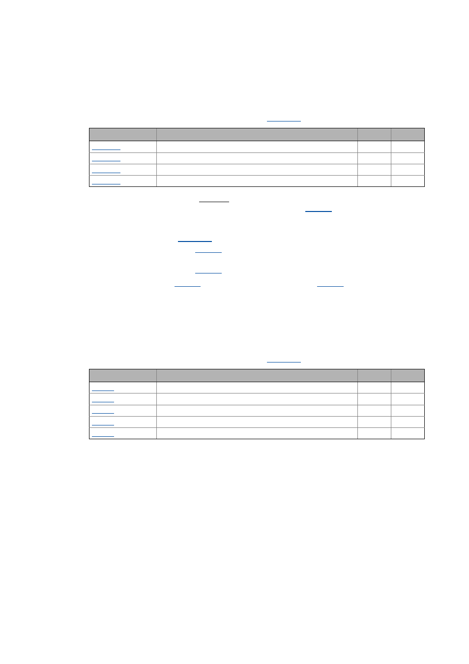
OPTIONAL: Automatic calculation of the speed controller parameters
From version 12.00.00 onwards:
Following successful motor parameter identification, the speed
controller parameters listed in the below table can also be calculated automatically.
• If these parameters are to be calculated, bit 6 of
must be set to "5".
• Care must be taken that the constant mass inertia of the drive (mass inertia of motor, gearbox,
shaft and constant load) is entered as exactly as possible in
controller parameters as dynamically as possible.
• Mass inertias that are not constant (e.g. changing loads of reels or different loads of hoists)
must be entered in
.
• If the mass inertia set in
is too low, the speed controller parameters are calculated
less dynamically.
• If the mass inertia set in
is too high, speed controller operation is unstable.
• If the mass inertia in
is set to "0", the setting of bit 5 in
speed controller parameter calculation. In this case, the speed controller parameters will not be
calculated automatically after motor parameter identification.
OPTIONAL: Automatic calculation of other controller parameters
From version 12.00.00 onwards:
Following successful motor parameter identification, the controller
parameters listed in the below table can also be calculated automatically.
• If these parameters are to be calculated, bit 6 of
must be set to "6".
Parameter
Info
ASM
PSM
SLVC: Vp speed controller
SLVC: Ti speed controller
SLPSM: Vp speed controller
SLPSM: Ti speed controller
Parameter
Info
ASM
PSM
Appl.: Reference speed
Imax in motor mode
Nact filter time constant
VFC: Time const. slip comp.
VFC-ECO: Voltage reduction ramp