8technology applications – Lenze 8400 TopLine User Manual
Page 495
Lenze · 8400 TopLine · Reference manual · DMS 6.0 EN · 06/2014 · TD05/TD14
495
8
Technology applications
8.4
TA "Table positioning"
_ _ _ _ _ _ _ _ _ _ _ _ _ _ _ _ _ _ _ _ _ _ _ _ _ _ _ _ _ _ _ _ _ _ _ _ _ _ _ _ _ _ _ _ _ _ _ _ _ _ _ _ _ _ _ _ _ _ _ _ _ _ _ _
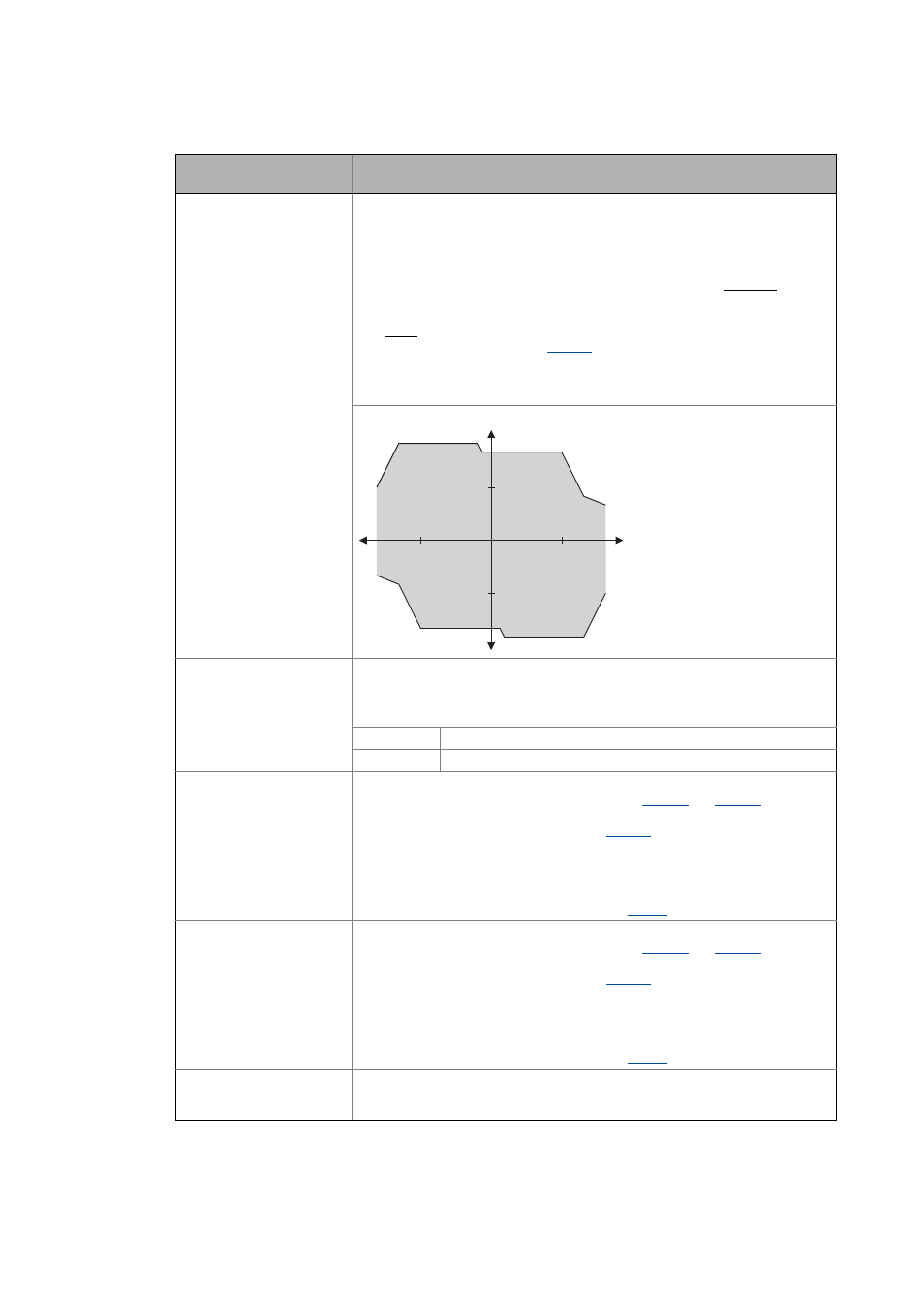
nTorqueMotLim_a
nTorqueGenLim_a
INT
Torque limitation in motor mode and in generator mode
• These input signals are directly transferred to the motor control to limit the
controller's maximum torque in motor and generator mode.
• The drive cannot output a higher torque in motor/generator mode than set here.
• The applied values (any polarity) are internally interpreted as absolute values.
• If V/f characteristic control (VFCplus) is selected, limitation is indirectly
performed via a so-called I
max
controller.
• If sensorless vector control (SLVC) or servo control (SC) is selected, limitation has
a direct effect on the torque-producing current component.
• Scaling: 16384 ≡ 100 % M
max
Note:
Setting this input is ineffective in the reference modes 14 and 15 ("Homing to
positive stop").
Torque limits in motor and generator mode:
bSetSpeedCcw
BOOL
Change of direction of rotation
• For instance if a motor or gearbox is fixed laterally reversed to a machine part, but
the setpoint selection should still be executed for the positive direction of
rotation.
FALSE Clockwise rotation (Cw)
TRUE Direction of rotation to the left (Ccw)
nMainSetValue_a
INT
Main speed setpoint
• Offset and gain of this input signal can be set in
signal adjustment of a setpoint encoder.
• Scaling: 16384 ≡ 100 % reference speed (
• The main setpoint is transformed to a speed setpoint in the setpoint encoder via
a ramp function generator with linear or S-shaped ramps.
• Upstream to the ramp function generator, a blocking speed masking function
and a setpoint MinMax limitation are effective.
• For a detailed functional description see the
FB.
nAuxSetValue_a
INT
Additional speed setpoint
• Offset and gain of this input signal can be set in
signal adjustment of a setpoint encoder.
• Scaling: 16384 ≡ 100 % reference speed (
• The additional speed setpoint can be linked arithmetically with the main speed
setpoint behind the ramp function generator.
• The additional speed setpoint can be shown via ramp times of a second ramp
function generator.
• For a detailed functional description see the
FB.
bJogSpeed1
bJogSpeed2
BOOL
Selection inputs for fixed changeover setpoints (JOG setpoints) for the main setpoint
• Selection inputs are binary coded.
Identifier
Data type
Information/possible settings
n
N
M
N
M
-M
N
-n
N
n
TorqueMotLim
TorqueGenLim
TorqueMotLim
TorqueMotLim
TorqueGenLim