1 pole position identification 360, Pole position identification 360, 6encoder/feedback system – Lenze 8400 TopLine User Manual
Page 360
6
Encoder/feedback system
6.5
Pole position identification (PPI)
360
Lenze · 8400 TopLine · Reference manual · DMS 6.0 EN · 06/2014 · TD05/TD14
_ _ _ _ _ _ _ _ _ _ _ _ _ _ _ _ _ _ _ _ _ _ _ _ _ _ _ _ _ _ _ _ _ _ _ _ _ _ _ _ _ _ _ _ _ _ _ _ _ _ _ _ _ _ _ _ _ _ _ _ _ _ _ _
6.5.1
Pole position identification 360°
Procedure for "pole position identification 360°"
If all conditions are met, the motor is energised with a direct current corresponding to the lower of
the following two values:
• The rotor is aligned through the current flow. This is absolutely necessary for the procedure.
• To ensure that the torque-neutral axis is not accidentally energised and the rotor stops, a 45°
current vector is (electrically) generated for a short instant and then (electrically) switched back
to 0° (≡ phase U).
• Then a DC current of the above-mentioned value could be measured in this motor phase.
• If a resolver or an optical encoder without absolute track is used, the difference between the
preselected current angle and the mechanical rotor angle is determined. After this, the current
vector is (electrically) turned by another 22.5° and the difference between current angle and
rotor angle is determined once again.
• The procedure is repeated 16 times. This corresponds to one electrical revolution. The
machine rotates by 360° (mech.)/pole pair number.
• Take the average value of the 16 measurements to compensate for asymmetries.
Adjustment of the pole position identification 360°
The pole position identification can be adjusted to the respective machine and the prevailing
moments of inertia by means of the parameters described below:
• The current amplitude can be adjusted proportionally in
.
• For large machines and high mass inertia values or for linear direct drives, the current
amplitude usually has to be increased.
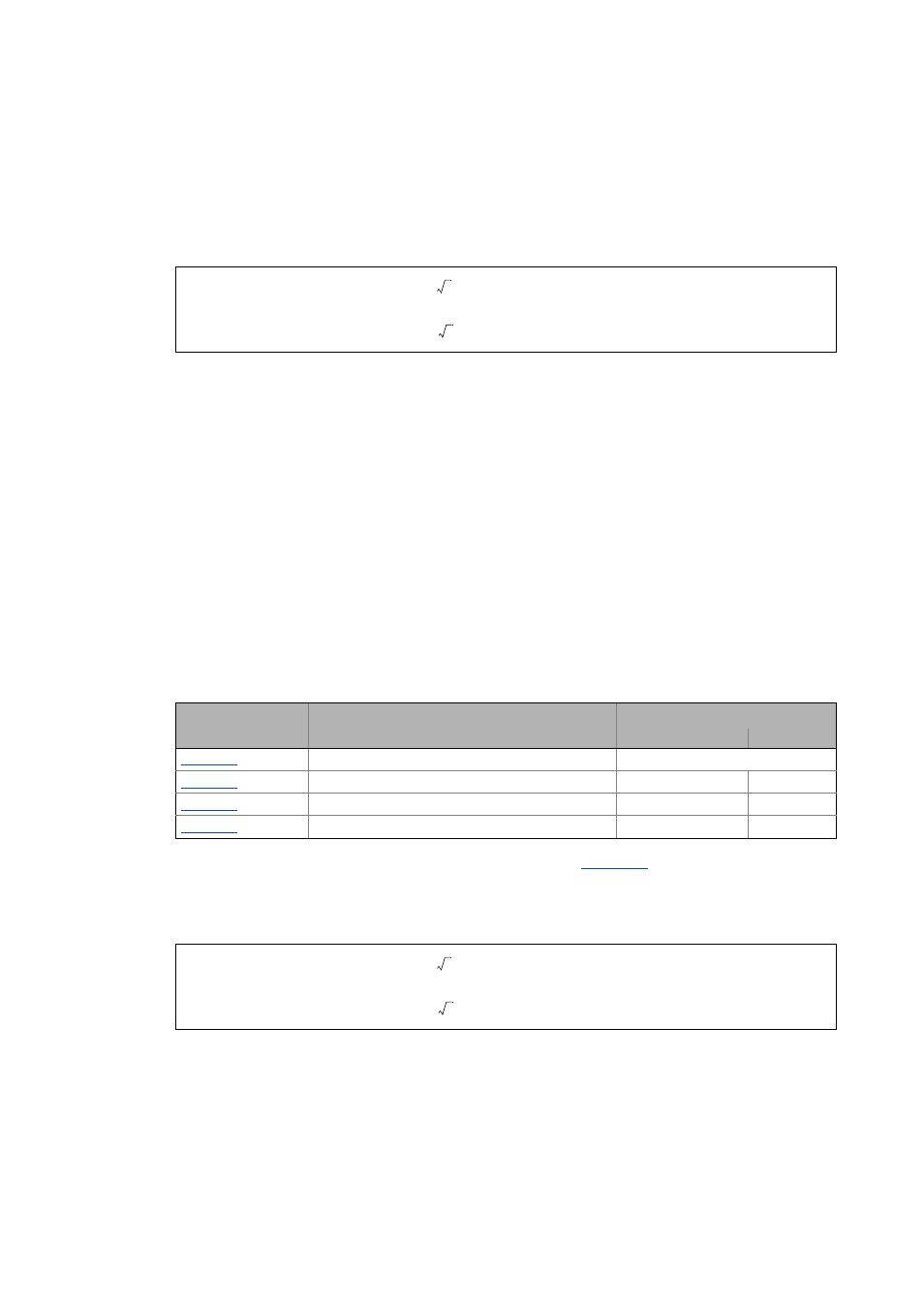
• The Lenze setting "100 %" corresponds to the smaller of the two following values:
or
Parameter
Info
Lenze setting
Value Unit
PLI 360° traversing direction
right rotating field
PLI 360° max. error tolerance
0.0 °
PLI 360° current amplitude
100 %
PLI 360° ramp time
100 %
or
2 Rated device current
⋅
2 Rated motor current
⋅
2 Rated device current
⋅
2 Rated motor current
⋅