10 diagnostics & error management – Lenze 8400 TopLine User Manual
Page 688
10
Diagnostics & error management
10.5
Logbook
688
Lenze · 8400 TopLine · Reference manual · DMS 6.0 EN · 06/2014 · TD05/TD14
_ _ _ _ _ _ _ _ _ _ _ _ _ _ _ _ _ _ _ _ _ _ _ _ _ _ _ _ _ _ _ _ _ _ _ _ _ _ _ _ _ _ _ _ _ _ _ _ _ _ _ _ _ _ _ _ _ _ _ _ _ _ _ _
• Additionally, a read access to different individual elements of the logbook entry addressed can
be executed via the subcodes of
. These parameters have a uniform data format (32 bits)
and represent the most important part of the logbook data:
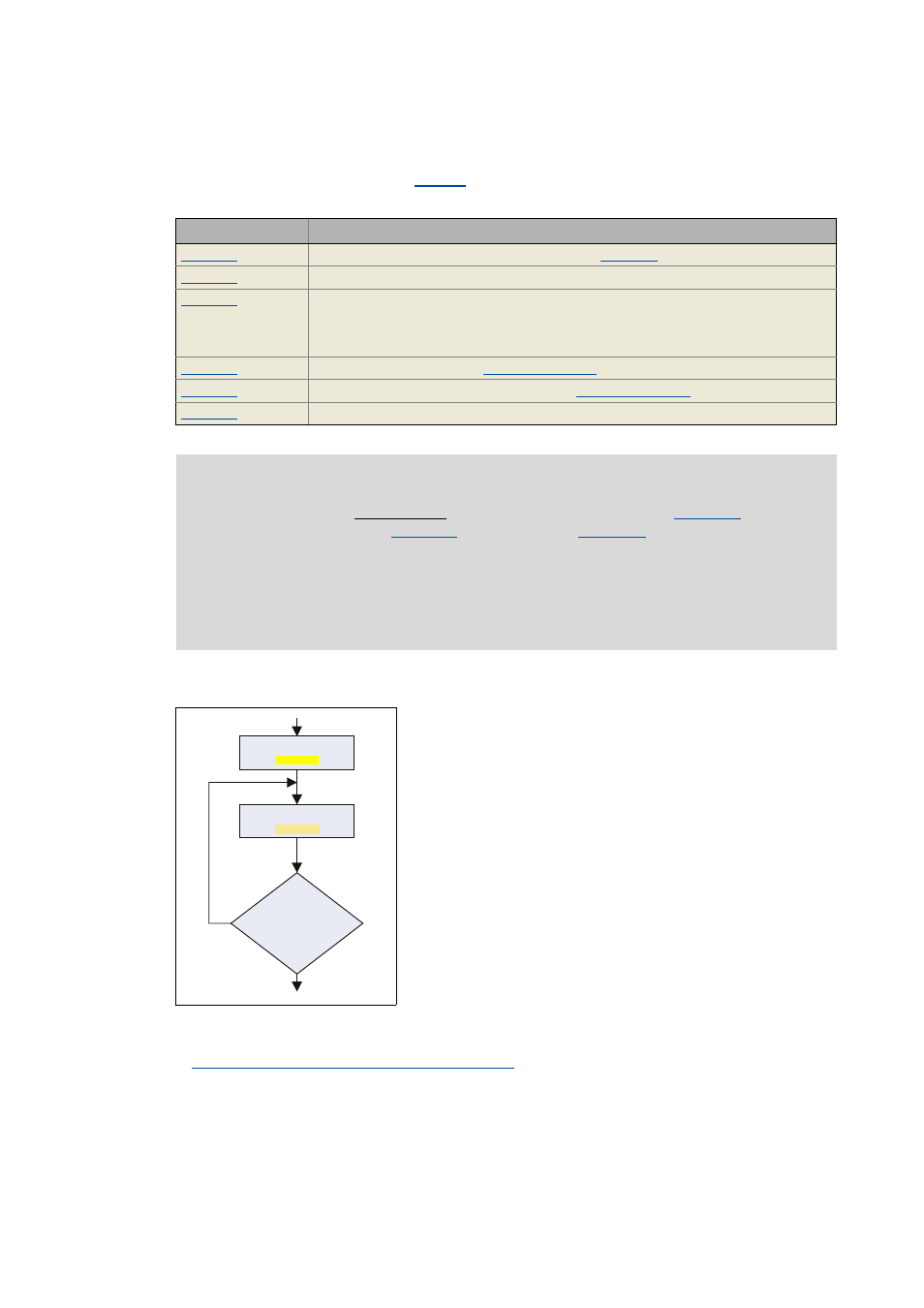
Basic workflow
Related topics:
Structure of the 32-bit error number (bit coding)
Parameter
Display
Response index, reference to the index requested (
)
Error activity flag (0 = error not active; 1 = error active)
Error counter (0 ... 255)
• This information depends on the logbook configuration. In the Lenze setting the logbook
configured so that identical errors do not produce a new line entry, but a counter is
incremented for this error.
Error type (bits 26 ... 29 of the
)
Error subject area + error ID (bits 0 ... 25 of the
Time in [s] during which the power was switched on (power-on time meter).
Note!
• In the case of a simultaneous read access to the logbook entry (
) and its
individual elements (
), the line index in
must only be reset by the
control after the read process is fully completed. Otherwise the data read are
inconsistent.
• Depending on the device version, the maximum number of logbook entries can vary:
• 8400 StateLine: 15 logbook entries
• 8400 HighLine/TopLine: 50 logbook entries
• The logbook can be read out by an external control or
visualisation via the procedure shown on the left.
• The "Response index" query ensures that the logbook entry
read really corresponds to the logbook entry requested.
:ULWH/RJOLQHLQGH[
&
5HDG/RJOLQH
&
/RJOLQH
UHVSRQVHLQGH[
/RJOLQH
LQGH["
1R