5motor control (mctrl) – Lenze 8400 TopLine User Manual
Page 287
Lenze · 8400 TopLine · Reference manual · DMS 6.0 EN · 06/2014 · TD05/TD14
287
5
Motor control (MCTRL)
5.12
Braking operation/brake energy management
_ _ _ _ _ _ _ _ _ _ _ _ _ _ _ _ _ _ _ _ _ _ _ _ _ _ _ _ _ _ _ _ _ _ _ _ _ _ _ _ _ _ _ _ _ _ _ _ _ _ _ _ _ _ _ _ _ _ _ _ _ _ _ _
Operating mode of the inverter motor brake
The ramp function generator is stopped during acceleration. The speed set in
is added to the
speed setpoint by means of a hysteresis-type 2-point DC bus voltage controller, whereby the sign of
the current actual speed is taken into account. In addition, the ramp function generator is stopped
during overvoltage.
If the DC bus voltage falls below a defined DC bus voltage potential of the hysteresis controller, the
added speed is subtracted again and the ramp function generator is activated again.
The energy is converted into heat in the motor due to alternating instances of acceleration and
deceleration as a result of this switching operation.
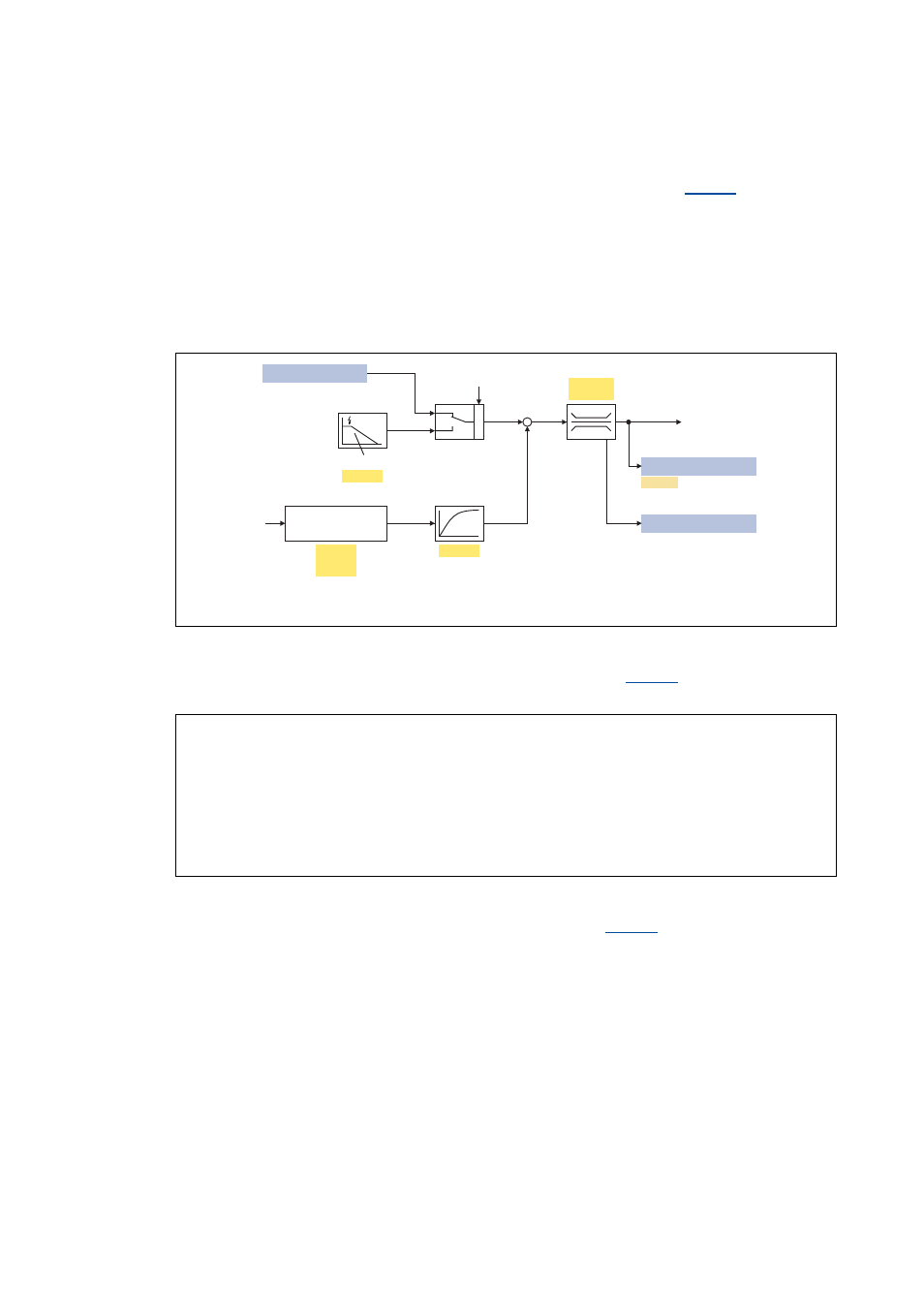
[5-30] Signal flow of the "Inverter motor brake" function
• In case of an asynchronous motor, the additive speed setpoint (
) should be 1 … 4 times
the slip of the machine:
[5-31] Formula for calculating the additive speed setpoint for an asynchronous motor
• In case of a synchronous motor, the additive speed setpoint (
) should be 5 … 20 % of the
rated machine speed.
DC-bus voltage
Speed setpoint for motor control
0
1
QSP
nSpeedSetValue_a
C00173
C00174
C00987
C00105
C00988
C00050
C00909/1
C00909/2
nEffSpeedSetValue_a
bLimSpeedSetVal
QSP ramp
Inverter
motor brake
p = number of pole pairs
n
Rat
= Rated speed of the motor
f
Rat
= Rated frequency of the motor
n
Sync
= Synchronous speed of the motor
C00987 [rpm]
1 ... 4 n
Sync
[rpm] n
Rated
[rpm]
–
(
)
⋅
=
n
Sync
[rpm]
f
Rated
Hz 60
⋅
p
--------------------------------
=