5motor control (mctrl) – Lenze 8400 TopLine User Manual
Page 290
5
Motor control (MCTRL)
5.12
Braking operation/brake energy management
290
Lenze · 8400 TopLine · Reference manual · DMS 6.0 EN · 06/2014 · TD05/TD14
_ _ _ _ _ _ _ _ _ _ _ _ _ _ _ _ _ _ _ _ _ _ _ _ _ _ _ _ _ _ _ _ _ _ _ _ _ _ _ _ _ _ _ _ _ _ _ _ _ _ _ _ _ _ _ _ _ _ _ _ _ _ _ _
Functional principle
One of the controllers of the DC-bus system is assigned the role of the "brake chopper master".
• For logical reasons, the "brake chopper master" should be the most powerful controller.
• The "brake chopper master" controls its internal brake chopper via the DC-bus voltage as before.
In addition, the "brake chopper master" transmits the bBrakeChopperActive status signal of its
internal brake chopper control to the other controllers of the DC-bus system via fieldbus or
digital output.
All other controllers of the DC-bus system are "brake chopper slaves".
• The "brake chopper slaves" have the bBrakeChopperActive status signal received from the "brake
chopper master" connected to the bBrakeChopperOn control input.
• If the internal brake transistor of the "brake chopper master" is switched on, the internal brake
transistors of the "brake chopper slaves" are switched on at the same time.
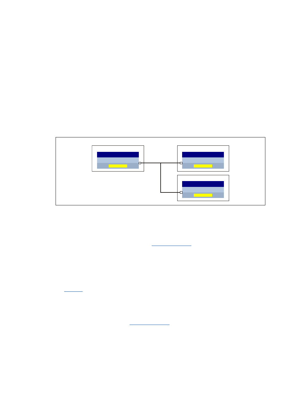
[5-32] Functional principle of the "Brake chopper master-slave operation" (simplified representation)
Procedure
1. Assign the role of the "brake chopper master" to one of the controllers of the DC-bus system.
2. Adapt the function block interconnection for the "brake chopper master" so that the
bBrakeChopperActive status signal of the
SB is provided to the other
controllers for controlling the internal brake chopper.
• The bBrakeChopperActive signal can e.g. be output via port block to the fieldbus or via digital
output.
• A free output of the application block can be used to transfer the signal from application level
to I/O level.
3. Configure all other controllers of the DC-bus system as "brake chopper slaves". Select "1: Yes" in
for these controllers.
• With this setting, the brake chopper is not controlled via the DC-bus voltage anymore. Its
control now depends on the bBrakeChopperOn control signal.
4. Adapt the function block interconnection for the "brake chopper slaves" so that the
bBrakeChopperActive signal received from the "brake chopper master" is connected to the
bBrakeChopperOn input of the
SB.
• Depending on the output at the "brake chopper master", the signal must be read in e.g. via
port block or digital input.
• A free input of the application block can be used to transfer the signal from I/O level to
application level.
• If the digital inputs/outputs are used for transmitting the signal, they must be connected
electrically accordingly.
%UDNHFKRSSHUPDVWHU
E%UDNH&KRSSHU$FWLYH
/6B0RWRU,QWHUIDFH
E%UDNH&KRSSHU2Q
/6B0RWRU,QWHUIDFH
&
&
%UDNHFKRSSHUVODYHV
E%UDNH&KRSSHU2Q
/6B0RWRU,QWHUIDFH
&