2 optimising resolver behaviour, Optimising resolver behaviour, Optimise resolver behaviour – Lenze 8400 TopLine User Manual
Page 321: 6encoder/feedback system
Lenze · 8400 TopLine · Reference manual · DMS 6.0 EN · 06/2014 · TD05/TD14
321
6
Encoder/feedback system
6.2
Resolver (X7)
_ _ _ _ _ _ _ _ _ _ _ _ _ _ _ _ _ _ _ _ _ _ _ _ _ _ _ _ _ _ _ _ _ _ _ _ _ _ _ _ _ _ _ _ _ _ _ _ _ _ _ _ _ _ _ _ _ _ _ _ _ _ _ _
6.2.2
Optimising resolver behaviour
Due to mounting and production tolerances as well as resolver material property leakage, errors
may occur which, among other things, result in speed-dependent vibration of the actual speed.
These errors are called resolver errors. Resolver errors typically occur in the form of the 1st and 2nd
harmonic. They have two different causes:
1. The inductances of the sine and cosine track of the resolver have slightly different values.
2. Sine and cosine track do not magnetise orthogonally to each other.
Resolver errors due to cause 1 can be corrected by adjusting the gains of the digital/analog
converters which feed the resolver tracks. In the Lenze setting, the gains of both resolver tracks are
preset with identical values.
Resolver errors due to cause 2 can be compensated for by a slight correction of the angle via which
both resolver tracks are fed relative to one another.
When the "Resolver error identification" device command (
) is executed, the gain of the
resolver signals and the angular drift of both resolver tracks is corrected to minimise the resolver
error.
• Select a speed-controlled operating mode (e.g. servo control) for your machine while you
perform a resolver error identification run. During the identification run, speed must be
constant and greater than 500 rpm.
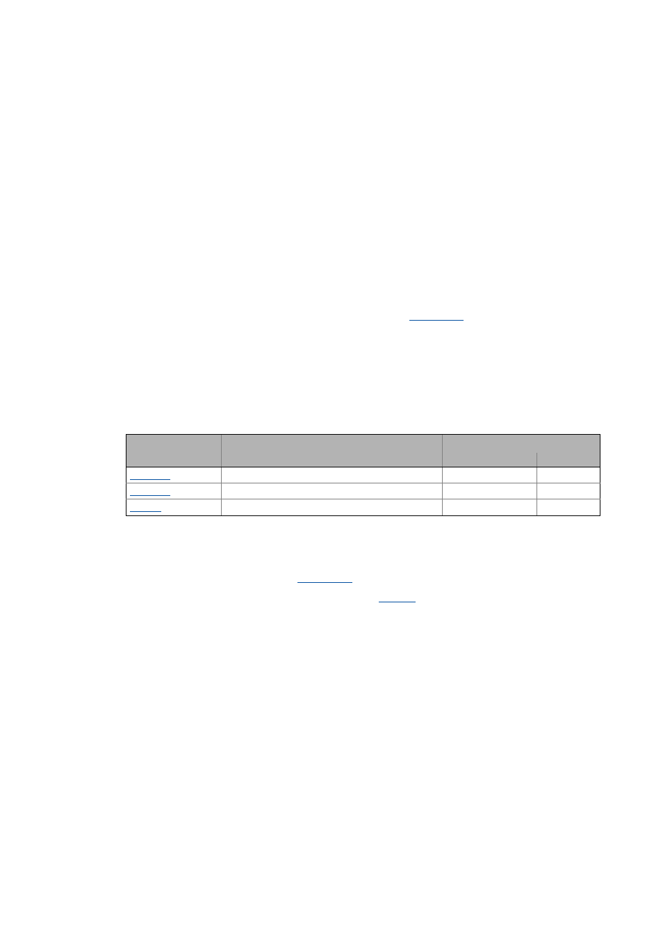
• After a successful resolver error identification run, the resolver automatically uses the following
resolver error parameters which have been identified during the procedure:
• The detected gain can have values from 80 ... 120 %. It makes sense to adjust only one of the two
gains during a resolver error compensation. The other one remains at 100 % (Lenze setting).
• Save the parameter set afterwards to accept the identified resolver error parameters
• If the resolver error compensation is deactivated (
= "1: Resolver error comp. deact."), the
resolver will resume work with the Lenze setting. However, the identified resolver error
parameters remain saved.
Parameter
Info
Lenze setting
Value Unit
Resolver: cos gain
100.00 %
Resolver: sine gain
100.00 %
Resolver: Phase error
0.00 %