3 angle correction in case of transmission errors, Angle correction in case of transmission errors 1, 19 function library – Lenze 8400 TopLine User Manual
Page 1541
Lenze · 8400 TopLine · Reference manual · DMS 6.0 EN · 06/2014 · TD05/TD14
1541
19
Function library
19.1
Function blocks
_ _ _ _ _ _ _ _ _ _ _ _ _ _ _ _ _ _ _ _ _ _ _ _ _ _ _ _ _ _ _ _ _ _ _ _ _ _ _ _ _ _ _ _ _ _ _ _ _ _ _ _ _ _ _ _ _ _ _ _ _ _ _ _
19.1.99.3 Angle correction in case of transmission errors
If an angular offset between master and slave is caused due to transmission errors (missing data
telegrams), it will be corrected by a catch-up function in the FB. For this purpose, the following
connections and parameter settings are required for the slave at the FB L_Interpolator_1:
1. The master angle of the master is connected to the dnPhiIn_p input.
2. The speed signal of the master is connected to the nNIn input.
3. The nNOut output is connected to the nSet_v input of the FB
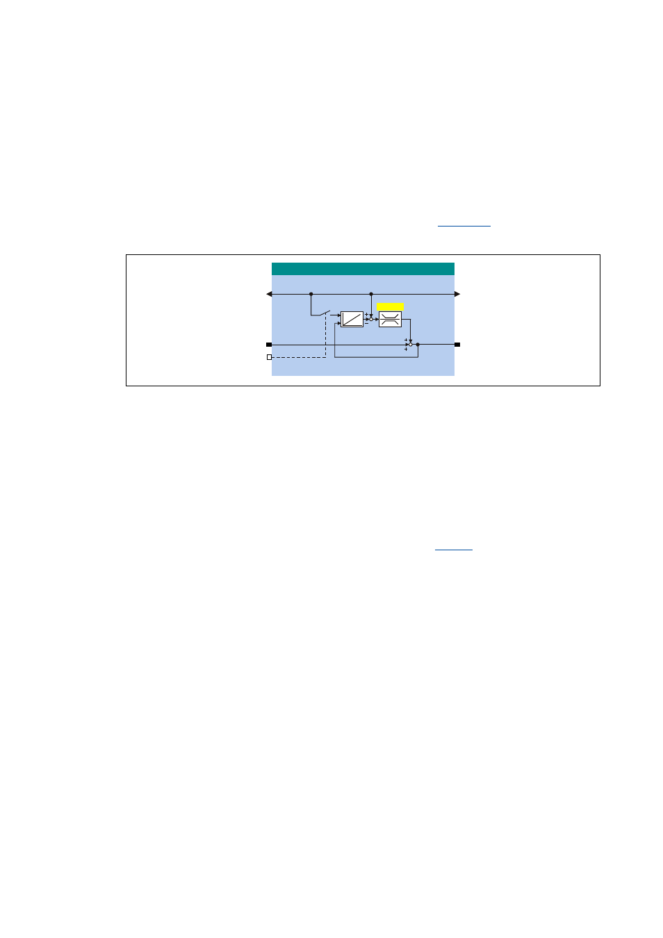
The following illustration shows the principle of the catch-up function in the FB L_Interpolator_1:
[19-42] Principle of the catch-up function
The speed signal at nNIn is provided almost 1:1 at the nNOut output. In case of a telegram error, a
correction value can be added to the signal. This correction value results from the subtraction of the
integrated speed signal from the position value applied at dnPhiIn_p.
If for instance a data telegram fails, the input values for a program cycle remain constant. In the
following cycle, the correct position and speed are pending again.
"Holding" the position at dnPhiIn_p results in a difference between the position values at dnPhiIn_p
and at the output of the integrator. This difference is added to the nNOut_a output signal.
In order that this angle correction does not lead to a strong jerk in the master value, the amount of
correction increments is limited per cycle (catch-up cycle) using
. A typical correction value
is for instance 10 increments/ms.
When the controller is inhibited, the integrator is to be loaded with the position value pending at
dnPhiIn_p by setting the bSpeedAct0 input to TRUE. When the controller is enabled, the nNOut
speed signal is integrated.
/B,QWHUSRODWRUB
GQ3KL2XWBS
GQ3KL,QBS
Q1,QBD
E6SHHG$FW
Q12XWBD
& 6SHHGXS